Posts

Soldering Components In-Line

Okay… we do our best to not take things for granted.  In all of our blog posts, we always try to give you as much fundamental information on the material that we are presenting.  Every once in a while, we get called out by our customers for not explaining something thoroughly.  This post is intended to fix this.  In a lot of our blog posts and wiring diagrams, we show components installed in-line with a MASTERCELL input or a connection to ground.

In our last blog post, we showed wiring a 10K pull up resistor on a brake-pedal switch.  You can see that blog post here.  In other blog posts, we’ve shown wiring diodes in-line between a trigger on an ECU and a MASTERCELL input.  You can click here to see a recent example blog post.  Someone just asked us an obvious question on our last blog post.  “How do I install the diode or the resistor in the wire”.  We’ll show you how.  This isn’t the only way to do this but it is our recommended way to do this.

There are three important factors to consider when installing an in-line component in a wire.  First, you need to have good electrical connection.  Second, you need to protect it mechanically.  Lastly, you need to protect the joint from the environment.

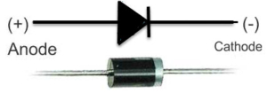
These steps will show you how to solder an axial, leaded component in-line with a wire.  A leaded part has metal terminals coming off its ends.  An axial part has the leads running along the axis of the component.  This picture shows you a good example of an axial, leaded diode.

Example of a simple diode

Example of a simple diode


Speaking of diodes, remember that they have a direction to them.  Check our wiring diagram for proper orientation of the diodes.  Resistors do not have a direction so you can install them either way in your wiring harness.

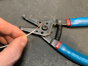
The first step is to strip back the insulation on the wire you’re connecting to your component.

Next, you want to twist the strands of the copper wire together.  This will make the next steps easier by keeping the strands together.

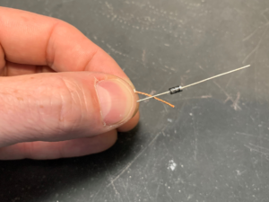
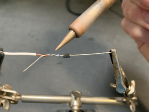
Next, twist the strands of the wire with the lead coming from your component.  We recommend leaving some length of the lead at the end as shown in this picture.

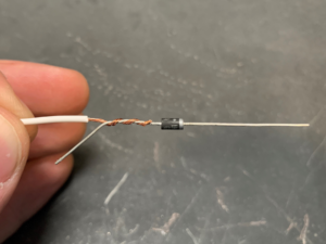
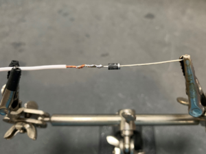
The next step is to make a good electrical connection between your wire and the lead on your component.  This needs to be soldered.  A good soldering iron and electrical solder will make this job easy.  You want to make sure that you are heating the joint thoroughly and that the solder is flowing between the copper wire and the lead on your component.  When you’re finished, the joint should be shiny.  If your joint looks grey or dull, you need to apply more heat and solder.  We also recommend keeping the solder on the joint between the copper wire and the lead on the component.  You do not want the solder to wick up the copper wire under the insulation.  This will make the joint inflexible and it could fail over time.

Once you have the joint soldered, clip off the extra length of lead on the component.

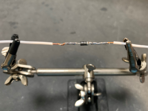
Repeat this process for the other side of your component.

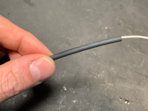
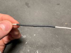
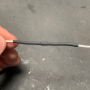
Now you have a good electrical connection between your wires and your component.  The next step is to protect the component mechanically and from the environment.  To do this, we recommend a good quality heat shrink tubing.  Heat shrink tubing does what its name suggests.  It shrinks around a joint when you heat it.  Cut a length of heat shrink tubing that is slightly larger in diameter than the component that you soldered in line.  You want the length of this tubing to extend past the exposed area of your joint by about 1/2″ on both sides.

Use a hot air gun to heat the tubing and shrink it over the component and the joints.  We know that a lot of guys like to use lighters or torches to do this but we really recommend a hot air gun for better control and safety.

The heat shrink tubing is going to do two important things.  First, it is going to mechanically strain relieve your joints.  This will keep the joints from failing due to vibration of mechanical stress.  We recommend that you zip tie these components in the harness to minimize any bending or movement as an added precaution.  Secondly, the heat shrink tubing is going to protect the joints from exposure to moisture, dirt and other chemicals in your car.

Soldering in-line components in your harness is a simple thing to do.  If you have any additional questions about this, please click on this link to contact our technical support team.



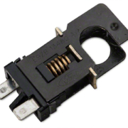
Picture of a lost-travel brake switch. Commonly found in Ford Mustangs.

+12 Volt Brake Light Signals

Our MASTERCELL uses ground switching to control all of the electrical functions in your car. There are many advantages to ground switching. You need less wire, you are only triggering a signal so the there is less current flowing through the switch and you can get the ability for combinational logic easily. This link will take you to a good description of how the MASTERCELL inputs work and how you should wire the switches connected to your Infinitybox system.  Your brake pedal switch is no different.  You run your MASTERCELL input for your brake lights to the switch on the pedal.  You connect your brake lights to the outputs on your rear POWERCELL.  When you step on the pedal, the MASTERCELL tells the rear POWERCELL to turn on the brake lights.  It’s pretty simple.  This blog post will get you more details on wiring your brake lights.  Normally, you’re going to use ground switching between your brake pedal switch and your MASTERCELL.  There are some times when you need a positive 12-volt signal from your brake pedal to interface with other electrical systems.  This blog post is going to show you a few easy options to get this +12 volt brake light signal.

There are several external electrical systems that need a positive signal from the brake pedal.  Examples of these systems include transmission controllers to manage the torque converter lock up.  Other examples include cruise control systems to disengage the system when you step on the brakes.  Another example is an external PKE system with one button start.  You must step on the brake pedal to safely start the car.  In a typical Infinitybox wiring set up, there is no battery voltage at the brake pedal switch.  An option to get this +12-volt signal would be to tap off the brake light on the rear POWERCELL.  This requires that you run a wire from the back of the car up to the front.  This may also be an issue if you’re using out 1-filament brake light set up.  We’re going to give you a few simple options to get this +12 volt brake light signal from the pedal to keep the wiring in your car short.

Before we get too far, you need to carefully read and understand the instructions for the electrical system that you’re interfacing with your Infinitybox system.  Make sure you know exactly what signal you need from your brake pedal switch.  Some systems need a +12-volt signal when you step on the brakes and a ground signal when your foot is off the pedal.  Other systems need a 12-volt signal when you’re foot is off the pedal and ground when you step on the pedal.  Make sure you understand what you need.  The following examples will show you how to accommodate any of these options.

The next thing that we need to review is the difference between Normally Open and Normally Closed switches.  These designations describe what the contacts in the switches are doing when the switch is in its normal state.  A Normally Open (NO) switch is off when you are not pushing it.  You have to push the switch to turn the switch on.  A Normally Closed (NC) switch is on when you are not pushing it and off when you push it.  The majority of the switches in your car are Normally Open (NO) but there are a few exceptions.

There are a few different types of brake pedal switches.  Two terminal switches are the most common.  There are also 4-terminal switches.  Within the 4-terminal switches, most of these have a set of Normally Open (NO) contacts and a set of Normally Closed (NC) contacts.

Let’s start with the 2-terminal switches.  These have a set of Normally Open contacts.  The switch is off when you are not pressing the brake pedal.  When you step on the pedal, you close the contacts.  This makes an electrical connection between the two terminals on the switch.  In a normal Infinitybox set up, you ground one of the terminals on the switch and connect the second terminal to the MASTERCELL input for your brake lights.  When you step on the brake pedal, you make an electrical connection between the MASTERCELL input and ground.  This is a very simple set up, however you don’t have +12 volts at the switch.

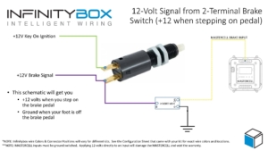
This diagram shows you how to wire your 2-terminal brake pedal switch to get a +12 volt signal and a ground signal for the MASTERCELL.  It uses an Infinitybox inVERT Mini to flip the 12-volt signal from the switch to ground the MASTERCELL input.

Instead of grounding one terminal on the brake pedal switch, connect it to the ignition output on your front POWERCELL.  When the ignition is on in the car, you will have voltage on this terminal on the switch.  You can splice into the ignition output wire on the POWERCELL or you can use one of our Infinitybox Splice Saver kits to make this connection.  You will then connect the second terminal on the brake pedal switch to your controller that needs the +12-volt signal when you step on the pedal.  On this second terminal, you will also connect the input wire for the inVERT Mini.  The black wire on the inVERT Mini gets connected to ground and the output wire connects to the MASTERCELL input for your brake lights.  It’s pretty simple.  You can download a PDF copy of this wiring diagram by clicking this link.

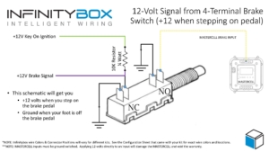
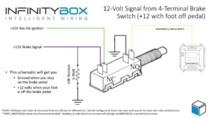
Another option is if you have a 4-terminal brake pedal switch.  These have two pairs of terminals.  Usually, the pair of terminals closest to the switch plunger are the Normally Open contacts.  They close when you step on the brake pedal.  The set of terminals furthest from the plunger is Normally Closed.  These contacts open when you step on the brake lights.  These diagrams assume that your switch has a Normally Open and a Normally Closed set of contacts.  Please confirm the type of switch that you have by checking resistance between the terminals with a multimeter.  You are going to use the Normally Open terminals to ground your MASTERCELL input for the brake lights.  Ground one of these terminals and connect the second terminal to the MASTERCELL input.

On the Normally Closed set of terminals, you are going to connect one of these to ground.  You then connect one end of a 10K (10,000 ohm) resistor to the second Normally Closed terminal.  The other end of the resistor should get connected to the ignition output on your front POWERCELL.  This resistor should be rated for at least 1/4 (0.25) Watts.  You can buy these easily from Amazon.  Just search for “1/4 watt 10k resistor”.  This picture will show you the connections that you need to make to your brake pedal switch.

When you are not stepping on the brake pedal, the brake signal wire terminal is pulled to ground by the fact that the terminals are closed.  The 10K resistor limits the amount of current flowing through the switch to less than 2 mA (0.002 amps).  When you step on the brake pedal, these contacts open and the brake signal wire is pulled up to the battery voltage through the 10K resistor.  You can download a PDF copy of this wiring diagram by clicking this link.

There are some scenarios where you need +12 volts when you foot is not on the brake pedal and ground when you step on the pedal.  This picture will show you how to wire the switch.

You are going to wire the MASTERCELL input and its ground the same way that you did for the other example.  Then connect one of the NC terminals on the switch to the ignition output on your POWERCELL.  Connect the second NC terminal on the switch to your brake signal connection.  Lastly, connect a 10K resistor (just like in the previous example) between the brake signal wire and ground.  When you foot is off the pedal, you’ll have 12-volts on the brake signal wire.  When you step on the pedal, the contacts in the switch open and disconnect the brake signal wire from ignition power.  The 10K resistor pulls the brake signal wire to ground.  You can download a PDF copy of this diagram by clicking this link.

Click on this link to contact our technical support team if you have any questions about getting a 12-volt brake pedal signal for your transmission controller, cruise control module or PKE system.

Wiring the Holley HP EFI System

This blog post goes through the details of wiring the Holley HP EFI System with our Infinitybox 20-Circuit Kit.  We will show you the ease and simplicity of wiring your EFI system with Infinitybox.  The wiring is simple and short and you can eliminate the need for external relays.  We’ll go through the key steps and give you a wiring diagram that shows you all the details to wire your Holley HP EFI Engine Management System with our Infinitybox system.

Before we get too far, you must thoroughly read and understand the instructions that came from Holley to install the HP EFI system.  Please consult their website to get the instillation instructions.  The other important thing to consider here is that we are going to show you how to connect your Infinitybox wiring system to the Holley HP.  This will include wiring the key-on ignition power, the cooling fan trigger and the fuel pump trigger.  Consult the Holley manual for all details regarding primary power from the battery, coil wiring, injector wiring, sensor wiring and grounds.  This diagram shows you the connections between your Infinitybox system and the Holley HP ECU.

Picture of wiring diagram showing how to wire Holley HP EFI system with the Infinitybox wiring system

Picture of wiring diagram showing how to wire Holley HP EFI system with the Infinitybox wiring system

Your Infinitybox 20-Circuit Kit powers the key electrical systems in your car.  We’re going to provide the key-on ignition power to the Holley HP system.  You are going to connect your POWERCELL ignition output to the 12V Switched wire in the Holley Harness.  This is their Red/White wire.  In most Infinitybox configurations, your ignition output is the light-green wire on your front POWERCELL but we encourage you to always use your configuration sheet to confirm wire colors in your specific kit.  You can get more details on your configuration sheet by clicking this link.  When you turn on your ignition switch, the POWERCELL will provide the key-on ignition power that the Holley HP needs to run.  You can learn more about wiring your ignition switch to your MASTERCELL by clicking this link.

You can use an output your Infinitybox rear POWERCELL to provide the power to your fuel pump.  There are several advantages to using the fuel pump output on your POWERCELL.  First, you do not need to use a relay.  The POWERCELL has the capability to control 25-amps to your fuel pump directly without a relay.  The second advantage is that you can power the fuel pump from the POWERCELL in the back of your car.  This keeps your wiring short and easy to install.  The Holley HP ECU has a fuel pump trigger that you can connect into the MASTERCELL input for your fuel pump.  The Holley fuel pump signal is +12 volts so you must use one of our inVERT Minis to flip this to a ground trigger to go into the MASTERCELL.  You can learn more about the inVERT Mini at this link.

You can also use an output on your Infinitybox front POWERCELL to power your cooling fan.  You get same benefits with your cooling fan as you do your fuel pump.  Your wiring is shorter and you do not need to use an external relay to control the fan.  You can either use a thermostatic switch on the engine or you can have the Holley HP ECU send the MASTERCELL the signal to control the fan.  This link will show you how wire in a thermostatic switch.  The Holley HP ECU has programmable outputs that can be used to signal the MASTERCELL input for the cooling fan.  You need to use one of their “G” or ground switched outputs and need to configure this within their software tool.  You must use a diode to isolate the output on the Holley HP from the MASTERCELL.  See the details in our wiring diagram.

Those are all of the connections that you need to make between your Infinitybox 20-Circuit Kit and the Holley HP EFI system.  You can download a PDF of this wiring diagram by clicking this link.

Click on this link to contact our technical support team if you have any questions about wiring your Holley HP EFI system with Infinitybox.

Jeep CJ7 Wiring Diagrams

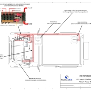
We’ve had our 1979 Jeep CJ7 on the road for a few years, fully wired with our Infinitybox system.  It is a great test vehicle for our products.  If you haven’t seen the install series for the Jeep, you can see all the details including the videos by clicking this link.  We created a full set of wiring diagrams showing how we wired the Jeep with our Infinitybox system.  These show where we mounted the cells, how we routed primary power from the battery and the CAN cables.  They also show how we wired all of the switches to the MASTERCELL and how we wired all of the loads to the POWERCELLs.  We also show the details of the dash lighting, the wiper wiring and the gauge wiring.  While these drawings show our Infinitybox system going into a Jeep, these diagrams are applicable for any resto-mod, street rod, kit car, hot rod or Pro-Touring build that you may be working on.

These links will take you to PDF copies of these wiring diagrams.

Infinitybox Jeep CJ7 Wiring Diagram- Cell Locations and Primary Power Routing

Infinitybox Jeep CJ7 Wiring Diagram- CAN Cable Routing

Infinitybox Jeep CJ7 Wiring Diagram- MASTERCELL Switch Wiring

Infinitybox Jeep CJ7 Wiring Diagram- POWERCELL Lighting Connections

Infinitybox Jeep CJ7 Wiring Diagram- Dash Lighting

Infinitybox Jeep CJ7 Wiring Diagram- Underhood POWERCELL Connections

Infinitybox Jeep CJ7 Wiring Diagram- Windshield Wiper Motor, Washer Pump and Heater Blower Wiring

Infinitybox Jeep CJ7 Wiring Diagram- Gauge Power and Sender Connections

You can see from these wiring diagrams how simple and streamlined the wiring is in the Jeep.

You can contact our team by clicking this link if you have any questions about wiring your car or truck with our Infinitybox system.  

1967 Camaro at SEMA Battle of the Builders

Jeremy, Tim and the entire team at Miranda Built did it again.  Their 1967 Camaro placed Top 10 in the Hot Rod category and Top 40 overall at the SEMA 2021 Battle of the Builders.  This is another beautiful example of their creativity, skill and attention to detail.  Our Infinitybox team is proud to be a part of this build.

1967 Camaro by Miranda Built Front

1967 Camaro by Miranda Built. Wired with the Infinitybox System.

The Camaro is powered by a supercharged LS3 into a TR6060 6-speed transmission.  It sits on a Roadster Shop chassis with a Ford 9″ rear end.  The attention to detail in this build is exceptional.

1967 Camaro by Miranda Built Engine Bay

1967 Camaro with supercharged LS3 by Miranda Built. Wired with the Infinitybox System.

They wired the car with our 20-Circuit Kit, inMOTION, inLINK and inRESERVE.  We always to a little custom code for the Miranda Built cars to add a few modern electrical touches.  Because of the distributed nature of the Infinitybox system, they can mount our MASTERCELL, POWERCELLs and inMOTION cells where they need them.  All of their wire runs are short and neat.  You can’t see any evidence of the wiring in this car.

1967 Camaro by Miranda Built Dash & Interior

1967 Camaro by Miranda Built. Wired with the Infinitybox System.

This video shows Jeremy Miranda walking through the details of this amazing car.  You can also get more details on the car from their website by clicking here.

We congratulation the Miranda Built team on this awesome win.  Great job guys!

If you want to learn more about how you can wire your car or truck with our Infinitybox system, click this link to talk to our team.


Haltech ECU Wiring Diagram

Here’s the answer to a question that we get asked a lot.  Will the Infinitybox system work with my ECU or EFI system?  The answer is always, YES.  We play nicely with everyone’s fuel injection system.  We recently received this question related to the Haltech Elite 950 ECU.  This blog post is going to show you how easy it is to wire this EFI set up with our Infinitybox system.

Just like anything else, please start by reading the instructions.  This blog post is going to cover the details of wiring the Haltech Elite 950 ECU with the Infinitybox 20-Circuit Kit.  We’re going to assume that you’re running our Front-Engine configuration.  If you’re running our Rear-Engine configuration, check your configuration sheet for the specific locations of the inputs and outputs referenced in this blog post.  The Haltech part number for this ECU is HT-150700 and you can get to its details at this link.    Read and understand their instructions before you get into wiring.

This blog post is going to show you how to get ignition power to their ECU.  It will also show you how to take the cooling fan and fuel pump triggers from the ECU into the MASTERCELL.  Lastly, this blog post will show you how wire in the power to the injectors and coils so you can eliminate the need for external relays.

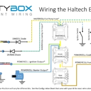
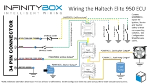
This diagram will show you the connections that you will make between your Infinitybox system and the Haltech ECU harness.

Haltech ECU Wiring Diagram with Infinitybox Control

Haltech ECU Wiring Diagram with Infinitybox Control

To start, the ECU needs to be grounded.  You need to take the black wire going to terminal 10 on the 34-pin connector and ground that.  This should be through a metal-to-metal connection to the chassis.  There should be no dirt, grease, oil, paint, rust, powder coating or anything else in this connection.

Next, the ECU needs key-on-power.  This power should be on when the key is in the run and start position.  You are going to get this power from the Ignition output on your POWERCELL.  In most kits, this is output 3, the green wire, on the front POWERCELL.  Check your configuration sheet for the wire colors for your specific kit.  Since your POWERCELLs manage all of the high-current switching in your electrical system, you do not need external relays to control your fuel injection system.  Connect your Ignition output from your POWERCELL to the “12V ECU” wire going to terminal 26 on the ECU harness.  This is the red wire with the blue tracer.

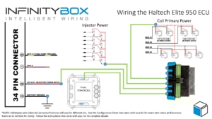
You can bring ignition power to the coils and the injectors from the Ignition output on your POWERCELL.  You can splice these wire together, use a terminal block or use our Splice Saver kit to make a reliable and sealed connection.  This diagram will show you how to connect the Splice Saver kit to your ignition output, the coils and the injector.

Infinitybox wiring diagram showing Haltech Key-On Power Wiring Details

Infinitybox wiring diagram showing Haltech Key-On Power Wiring Details

Next you are going to connect the outputs on the Haltech ECU for the fuel pump and the cooling fan to their inputs on the MASTERCELL.  Haltech dedicates DPO 5 for the fuel pump.  You can connect that to your MASTERCELL Input for your fuel pump.  We strongly recommend isolating the MASTERCELL from the ECU with a 1N4001 diode.  The orientation of this diode is very important.  Refer to the diagram above to show proper orientation of the anode and cathode of this diode.

You can use any of the other digital outputs on the Haltech ECU to trigger the MASTERCELL input for the cooling fan.  You must isolate the ECU from the MASTERCELL using a 1N4001 diode like the fuel pump.  We chose DPO 2 in our diagram.  You can use any of the available digital outputs however you must set them up correctly in their programming application.

Please note that you cannot pulse the DPO signal from the ECU that goes into the MASTERCELL for the fuel pump or the cooling fan.  These should be on and off signals to turn the pump and fan on and off.

You can download a PDF version of our wiring diagram for the Haltech Elite 950 ECU by clicking this link.

You can contact our technical support team with any questions by clicking this link.

System Current Draw

When you wire your car or truck with our Infinitybox system, you are adding a powerful electrical management system to your build.  We do so much more than a traditional wiring harness.  Our system has the power and intelligence to get you modern electrical control of your muscle car, restoration, street-rod, hot-rod, resto-mod, pro-touring car or race car.  Your Infinitybox system is awake and alive continuously so that it can respond immediately when you want to start the car, pop your trunk from our inLINK key fobs or control the system from your smart phone.

Wiring your car with the Infinitybox system gets you features that you cannot get from any traditional wiring harness but it does require more care & feeding.  Our system does have a parasitic draw on your battery when the car is sitting idle.  This is different than a traditional box of fuses and relays that has no active electronics in it.  We strongly recommend that you have a way to manage your battery for when you are not driving your car or truck.  There are three ways you can do this.

First, we always recommend a disconnect switch at the battery.  This is a quick and reliable way to disconnect the battery from your car’s electrical system.  This is a good idea for any car, even if you are not using the Infinitybox system to wire your car.  Other electronics systems that you add to your car, like electronic fuel injection systems, stereo equipment, will have parasitic draws from the battery.  A disconnect will help to keep your battery voltage up when you’re not driving the car.

Second, we always recommend some kind of trickle charger or maintainer for your battery for when your car is sitting idle.  This is true for any car, not just cars wired with our Infinitybox system.  You have many options for maintainer chargers from brands like Battery Tender, CTEK  and Schumacher.  Battery maintainers keep your battery voltage at its optimum level when the car is idle.  This will dramatically increase the life and reliability of your battery.

Lastly, our Infinitybox system has a unique accessory called inRESERVE.  inRESERVE is our active battery management feature.  The core of inRESERVE is a special latching solenoid that connects to a POWERCELL output.  The Infinitybox system is always watching and monitoring the battery voltage.  If the system sees the voltage start to get low, the POWERCELL sends a pulse to the special inRESERVE solenoid and disconnects all of the drain from the battery.  We build a lot of safety features into this system.  inRESERVE actively does its job if the battery drops below 12.3 volts, with the ignition off and stays at that level for 15 minutes.  This video talks through inRESERVE in more detail.

inRESERVE also gets you the disconnect feature that we mentioned in our first point above.  You can simply press the button included with your inRESERVE kit to disconnect the battery.  This adds a great security feature and lets you shut down power if the car is going to be sitting for extended periods of time.

We get a lot of questions about how much current the different components in the Infinitybox system draw when idle.  The MASTERCELL, POWERCELL and inMOTION cell each draw approximately 30 milliamps (0.03 amps) when they are powered up.  Adding the inLINK option adds approximately 10 milliamps to the MASTERCELL draw.  inVIRONMENT is in the range of 25 milliamps.  inTOUCH NET will draw 200 to 250 milliamps.

Please contact our team with any questions about the idle current draw of our Infinitybox system.  You can call us directly at (847) 232-1991 or you can click here to contact our team directly.


Jeep CJ7 Wiring Series- Mounting MASTERCELL

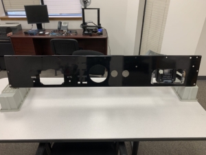
We’re progressing on wiring our 1979 Jeep CJ7 with our Infinitybox system.  We spent some time this weekend fabricating the mounts to hold the MASTERCELL.  In a previous update, we found the best location for the MASTERCELL.  We wanted it in a location that was close to our switches.  That makes the input wires short and easy to run.  We also wanted it located in a place that was easy to access for troubleshooting.  Locating the MASTERCELL behind the glovebox door was the ideal location.  You can catch that earlier video update at this link.  

Location of MASTERCELL behind dash of 1979 Jeep CJ7

Location of MASTERCELL behind dash of 1979 Jeep CJ7

The glovebox is small and generally useless in the Jeep.  It is also unsecure.  We’re going to be installing a locking center console for security later in the project.  When you take out the plastic glovebox, there is a good amount of space between the dash and the heater box.  That is a perfect location for the MASTERCELL.  We can simply open the glovebox door to access the MASTERCELL for troubleshooting and any updates that we’d want to make.

We bought a new dash panel from Quadratech.  They’ve been a great resource for a lot of the Jeep-related parts that we’ve needed over the project.  We have the dash on a bench in our lab and we’re going to do most of the wiring remotely.  Once the dash is done, we’ll drop that into the Jeep and make the connections to the POWERCELLs and other things with simple connectors.

Infinitybox MASTERCELL temporarily mounted behind dash in 1979 Jeep CJ7

Infinitybox MASTERCELL temporarily mounted behind dash in 1979 Jeep CJ7

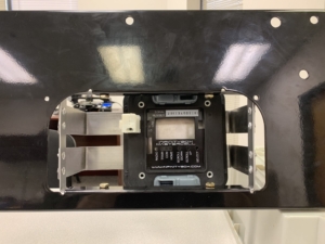
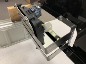
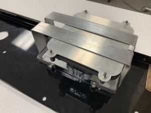
We fabricated a few simple straps from 1/16″ low-carbon steel.  The two vertical straps bolt into the existing dash holes for the deleted glovebox.  The two horizontal straps are riveted to the vertical straps.  The MASTERCELL mounting plate will be riveted to these horizontal straps.

Mounting bracket to hold Infinitybox MASTERCELL behind dash in 1979 Jeep CJ7

Mounting bracket to hold Infinitybox MASTERCELL behind dash in 1979 Jeep CJ7

Mounting bracket to hold Infinitybox MASTERCELL behind dash in 1979 Jeep CJ7

Mounting bracket to hold Infinitybox MASTERCELL behind dash in 1979 Jeep CJ7

For now, we have the MASTERCELL mounting plate held to the horizontal straps with double-sided tape.  We’ll permanently mount these parts together after we paint the straps and double-check the clearances behind the dash.

The end product is clean, rock solid and will properly support the MASTERCELL under all driving conditions.  All of the dash and switch wiring will be clean and short.  The MASTERCELL will be accessible for anything that we need.  Keep checking back for updates.  In our next steps, we’re going to be wiring the rest of the things on the dash.  This includes the headlight switch wiring, the gauges and the wiring going to the steering column.

You can catch the entire Jeep wiring series by clicking this link.  

You can also contact our technical support team with any questions by clicking this link.  


Jeep CJ7 Wiring Series- MASTERCELL Location

Over the next few videos, we’re going to continue our theme on good planning.  Specifically, we’re going to talk about picking the best locations for the major components that come with your Infinitybox system.  We’re installing our 20-Circuit Kit with inLINK and inRESERVE in our 1979 CJ7.  To get the most out of our install, we want to pick the best locations for the MASTERCELL, the front & rear POWERCELLs, the MEGA fuse holder and the inRESERVE solenoid.  We’ve broken this up into 5 different videos, talking about what you need to consider for each part.  This video covers picking the best location for your MASTERCELL.

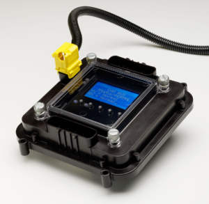
The Infinitybox MASTERCELL

The Infinitybox MASTERCELL

The MASTERCELL is the brain of your 20-Circuit Kit.  It connects to all of your switches.  These include your ignition switch, turn signal stalk, brake pedal switch, headlight switch, fuel pump & cooling fan trigger and any other accessory switches that you may have in your car or truck.  The MASTERCELL sends commands to the POWERCELLs when you turn a switch on or off.  You can learn more about the MASTERCELL and what it does by clicking this link.

There are two important things to consider when you’re picking the location for your MASTERCELL.  First, you want the MASTERCELL as close to your switches as possible.  This keeps the wiring short and makes it easy to install.  Second, you want to have easy access to the MASTERCELL for troubleshooting and diagnostics.  There are tons of diagnostic features built into the MASTERCELL.  You can learn about them at this link.  To access these features, you need to be able to get to the MASTERCELL, remove the protective cover, press the buttons and read the inSIGHT LCD screen.

In our 1979 Jeep CJ7, we’re going to mount the MASTERCELL in the glove compartment.  There is a convenient open pocket behind the door for the glove compartment.  This puts the MASTERCELL close to all of the switches on the dash.  That will make the dash wiring short and efficient.  With the door open, we can easily take off the MASTERCELL cover, press the buttons and read the inSIGHT screen.  When we close the door, the MASTERCELL disappears.

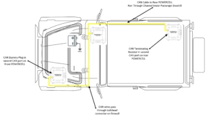
This picture will show the location of the MASTERCELL and POWERCELLs in the Jeep and how we routed the CAN cable between the cells.

Infinitybox Jeep CJ7 Wiring Diagram- CAN Cable Routing

Infinitybox Jeep CJ7 Wiring Diagram- CAN Cable Routing

Picking the best location for your MASTERCELL will make your switch wiring simple and efficient.  It will also make troubleshooting and diagnostics easier if you need them.  Keep watching for more in our 1979 Jeep CJ7 Install Series.

Be sure to subscribe to our YouTube channel and click the bell icon so you get notified when we post new videos in the series.

Click on this link to get to the main page for the 1979 Jeep CJ7 wiring project.  You can find all of the videos on one place there.  

You can also click here to contact our technical support team with any questions about your car or truck wiring project.  

Infinitybox CAD Models

Our customers are a unique breed of builder and fabricator.  They wire their cars and trucks with our Infinitybox system for a lot of different reasons.  To start, our system lets them simplify their wiring.  More importantly, our customers want more than just a plain, basic electrical system.  They want the same electrical features in their project that they have in their new, daily driver.  Our Infinitybox system lets them do that.  Since our customers are tinkers, makers and builders, they are using the latest solid modeling technology to virtually mock up their cars and trucks to make the project go more smoothly.  We get a lot of requests for CAD models for our cells, so we’ve made them available to our customers.

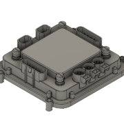
The introduction of on-line CAD tools like Audodesk’s Fusion 360 gives anyone in their garage access to very powerful and intuitive solid modeling tools.  You can import the CAD models for the Infinitybox MASTERCELLPOWERCELL and inMOTION cells into your projects.  You can check fitment, verify wire routing and make sure that you can access the cells, all in the computer before you cut any metal.

We have the solid models for the MASTERCELL, POWERCELL and inMOTION cells available in STEP and IGES formats.  Click on this link to contact our technical support team and we will send you the models.