We’re progressing through the different switches that need to get wired to the MASTERCELL in our customer’s 1967 Mustang. They are wiring their car with our 20-Circuit Kit. The last post covered the brake pedal switch, which is one of the easiest. In this post, we’re going to talk about how you figure out which switch terminals you need to connect to your MASTERCELL inputs.
Some switches are really easy, the brake pedal switch is an example. Others, we have created wiring diagrams for you to use. Our Resources section of our website has a long list of turn signal switches, ignition switches and headlight switches from different makes of car. You can find these under the Installation Guides section at this link.
There are some switches that are unique to a model year or are unique to a specific car. We may not have a wiring diagram assembled for your specific switch. It is usually pretty simple to figure out how to connect these switches to your MASTERCELL inputs. We’ll talk about the basics in this blog post.
Remember how a MASTERCELL input works. The MASTERCELL input gets triggered by getting connected to ground through the switch. In the case of the brake switch from our last post, that one was easy. One of the switch terminals connected to the MASTERCELL input. The other of the switch terminals connected to ground.
There are a few simple steps to follow to figure out which switch terminals you need to connect to for a new switch.
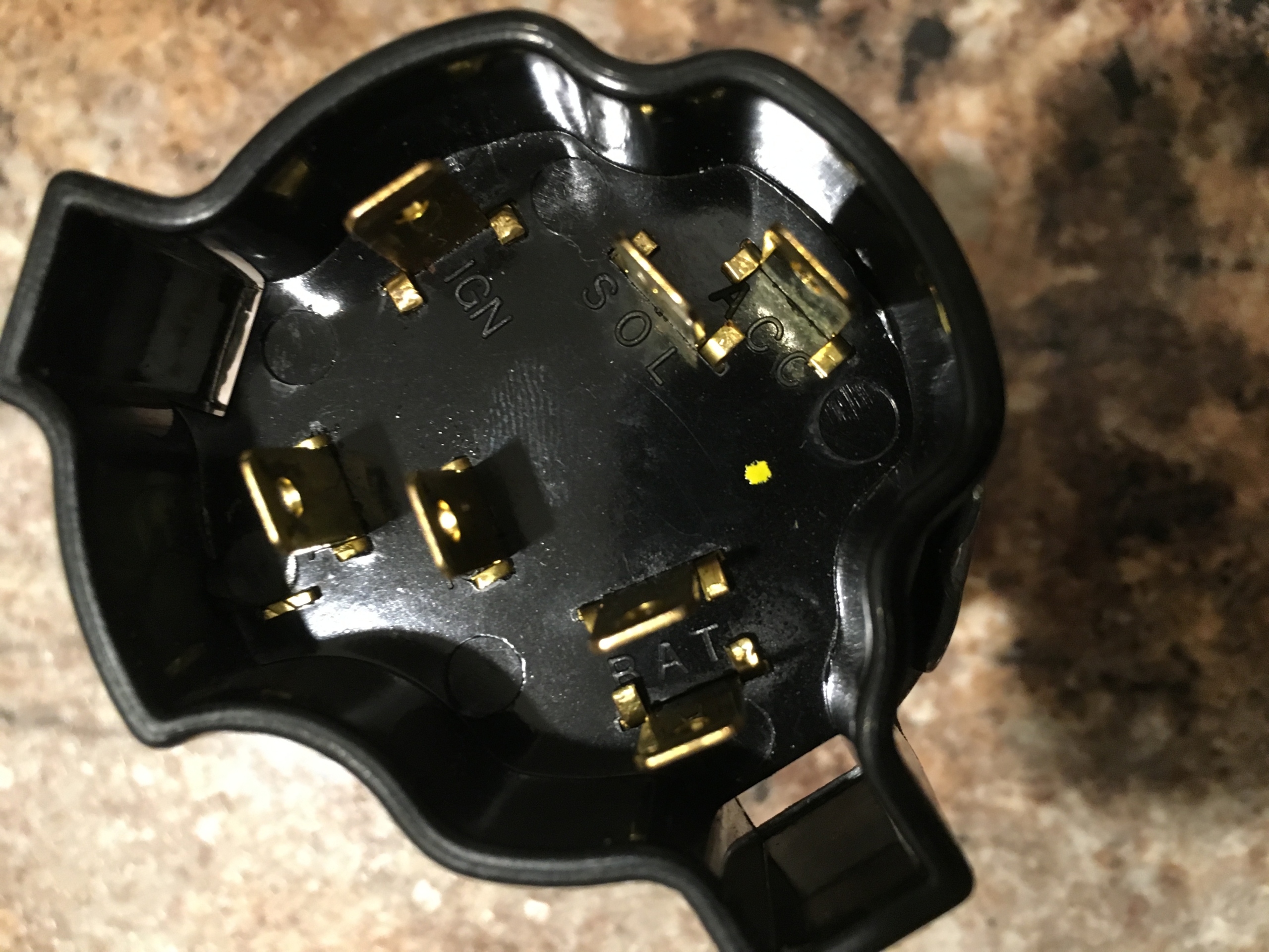
The first step is to find out where power came into the switch originally. Let’s use this switch as an example. One of our customers is wiring a 1972 Chevy truck with our 20-Circuit Kit. He sent us this picture of his ignition switch.
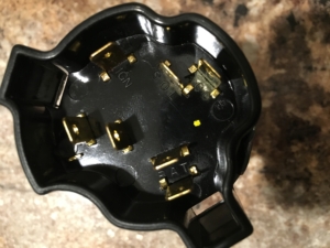
Picture of a typical Chevy truck ignition switch.
He didn’t know how to connect his MASTERCELL inputs to the switch terminals on the switch. If you look at the terminals on the switch, there are two labeled BAT. These are in the lower right corner of the picture. In most cases, BAT is where the battery originally connected to the switch. Ignition switches usually have two separate battery feeds: a dedicated one for the starter solenoid and one for the ignition feed.
You will also see that there is a terminal labeled IGN and one for SOL. At a first glance, you can assume that these are for the ignition power and starter solenoid feeds.
You are looking for terminals that have continuity between them when the switch is on. In the case of this ignition switch, you need to find the terminals that have continuity when the switch is in the run position for the ignition input. You also have to find the pair that have continuity in the start position for the starter input.
If you can, search the internet to see if you can find wiring diagrams for that specific switch. We’re always surprised to find that there is a forum or chat group for practically any type of car out there. Someone has worked on that switch before you and they have posted some wiring diagrams.
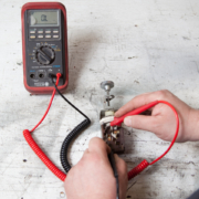
Once you have identified the terminals on the switch, get a multi-meter and check continuity between the terminals. If you don’t already have one, a good multi-meter is a powerful tool to have in the shop. The two most critical things that you have to measure would be voltage and resistance. Here is a simple meter that you can source from Waytek Wire. Here is an example of a meter from Del City.
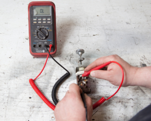
Picture showing how to use a multimeter to check continuity between terminals on a headlight switch
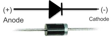
To figure out our switch terminals, we want to measure continuity or resistance. If a circuit has continuity, it should have low resistance between the terminals. Low should be less than 1 Ohm. Look for the resistance setting on your meter. On most meters, this is represented by the Greek letter Omega that looks like this: Ω.

Represents electrical resistance
Some meters have an auto-range function that will internally adjust to select the right range to measure resistance. Others have a dial to select the range. You want to set the range of your resistance measurement to the lowest range. To measure resistance, it really doesn’t matter if you have the red or black leads from the meter touching the different terminals.
Touch the test leads from your meter to the terminals with the switch in the off position. You should measure very high resistance or no change in resistance. In the case of this 1972 Chevy ignition switch, we were measuring between each of the BAT terminals and the IGN terminal with the switch off. We repeated this by measuring between each of the BAT terminals and the SOL terminal. We measured a resistance in the mega-ohm range. Some meters will show this as “OL” or “overload”.
We then turned the switch to the ON position and measured between the BAT terminals and the IGN terminal. We found that we had about 0.4 Ohms of resistance between the inner BAT terminal and the IGN terminal when the switch was in the ON position. In the case of this switch, we will connect the MASTERCELL ignition input wire to the IGN terminal and connect one of the ground wires from the MASTERCELL input harness to the inner BAT terminal. When the switch is in the ON position, there is continuity between IGN and the inner BAT terminal. This will ground the MASTERCELL input, which will turn on the Ignition output on the POWERCELL.
We repeated this for the SOL terminal. We measured between SOL and both of the BAT terminals when the switch was in the START position. We found that the outer BAT terminal was connected to the SOL terminal in the start position. We will connect the MASTERCELL input wire for the starter to the SOL terminal and connect one of the MASTERCELL ground wires to the outer BAT terminal. When the key is in the START position, there is continuity between the SOL terminal and the outer BAT terminal. This will ground the MASTERCELL input for the starter, which will turn on the starter output on the POWERCELL.
Just as a sanity check, we went back and measured resistance between the IGN terminal and the inner BAT terminal when the switch was in the START position. When the switch is in the START position, you must still have continuity between the IGN terminal and its ground connection so that the engine will start. The IGN terminal has continuity to its ground connection when the key is in the start position.
Figuring out how to wire your switch to your MASTERCELL inputs can be scary. We’ve built a large of list of different switches over the years but the steps above will help you to figure out any switch in your car. Click on this link to contact our team with questions.
 Copyright Infinitybox, LLC 2021. All Rights Reserved.
  Copyright Infinitybox, LLC 2021. All Rights Reserved.
  Copyright Infinitybox, LLC 2021. All Rights Reserved.

 Copyright Infinitybox, LLC 2021. All Rights Reserved.


 Copyright Infinitybox, LLC 2021. All Rights Reserved.
 Copyright Infinitybox, LLC 2021. All Rights Reserved.

 Copyright Infinitybox, LLC 2021. All Rights Reserved.