Configuration Sheet
The Configuration Sheet is your road map to wiring the car with the Infinitybox 20-Circuit Kit. It it included in the box and tells you the wire colors that connect to your switches and to your switched outputs. This is a really important document so let’s spend a few minutes reviewing it.
All of the MASTERCELL input wires and POWERCELL output wires are color coded. The same is true for the inMOTION output harnesses. You are going to use the Configuration Sheet to pair these input and output wires to their switches and the outputs.
Depending on the kit that you ordered and the accessories that you have, your configuration sheet is going to be unique to your system. Likewise, you’ll have a configuration sheet that is specific to you if we did custom programming for your system. We also have different configuration sheets for where the engine is located in the car. The Front-Engine configuration is our most common and is probably the most self-explanatory. This is used for cars where the engine is in the front of the car. The outputs for the ignition and starter are on the front POWERCELL.
If you are building a mid-engine or rear-engine car, you’d use the Rear-Engine configuration. The outputs for the ignition and starter are on the rear POWERCELL.
We also have specific configurations for component cars made by Factory Five. These include kits specifically configured for the Hot Rod, the GTM and the 818. These are based on things that we have learned from hundreds of systems that we sold into guys building these cars. If you’re building the MK4 Roadster or the Type 65 Coupe, you’d use the standard Front-Engine configuration.
This link will take you to the different configuration sheets for our Infinitybox system.
If you have lost your configuration sheet and need help locating the correct one, click here to contact our team for support.
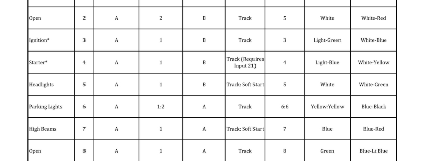
Let’s take a look at an example. This picture from a configuration sheet showing the details for the Headlights. Click on this image to blow it up to see the detail.
The first column is Function. This describes what is being controlled. You’ll see that there are rows for your ignition, starter solenoid, head lights, parking lights, high-beams, horn, cooling fan, turn signals, 4-ways and brake lights. There are also rows that marked as OPEN. These are generic and can be used for any other accessory that you have in your car.
The next column is Switch Input. This is the number that we use to identify the MASTERCELL inputs. There are 48 inputs on a MASTERCELL. Please note that the input number does not line up with the cavity marking on the input connectors. Click on this link to get a document that connects the MASTERCELL input number to the cavity marking on the connector. The MASTERCELL input wires are going to connect to the switches in your car. We’ll talk about that in a later post.
The next column is MASTERCELL Connector. There are two input connectors for a MASTERCELL, each has 24 inputs. The majority of your inputs will be on the A connector which plugs in the socket above the MASTERCELL screen. For systems with accessories like inMOTION and additional POWERCELLs, you will be using the B connector which is located below the MASTERCELL screen. Some kits do not come with this MASTERCELL B harness.
The next column is POWERCELL Address. This tells you which POWERCELL has the output that will turn on with that input. In the case of our headlight example, the POWERCELL address is 1. This means that the headlight output is on the front POWERCELL. You will see that there are some rows with POWERCELL address that say 1:2. This means that outputs on both POWERCELL 1 and POWERCELL 2 will turn on with this input. Examples include parking lights, turn signals and 4-ways. This link will show you how to set your POWERCELL addresses.
The next column is POWERCELL Connector. Just like the MASTERCELL, there is an A & B output connector on the POWERCELLs. In the case of our headlight example, the headlight output is on the B POWERCELL connector. Your manual will show you which output harness plugs into which socket on the POWERCELL.
Next you get the Personality column. This describes how the output will act when the input is turned on. This separate blog post will get you more information on output personalities. Click here to see it. In the case of the headlight example, the output will track the input and it will soft-start.
Next you get the POWERCELL Output column. This describes the number of the output on the POWERCELL that is turned on with the input on that row. For our headlights, that is output number 5.
The last two columns are the most important and most practical. Ignoring everything to the left, these two columns tell you the MASTERCELL input wire color and the POWERCELL output wire color. For the headlights, you are going to connect the White wire with the Green tracer to the headlight switch. You are going then take the White wire from the POWERCELL and connect that to your headlights. When you turn on the headlight switch, the White-Green wire will get grounded by the switch. The MASTERCELL sees this input turn. It sends a command to the POWERCELL to turn on the headlight output. This is the white wire.
This is one of the areas where our Infinitybox system is dramatically different from a traditional wiring harness. Your switches connect to the MASTERCELL. Your lights, fans, pumps, ECU’s, starter solenoid and other outputs connect to the POWERCELL.
There is a video on our YouTube channel that goes through the configuration sheet in more detail. You can catch this video below.

 Copyright Infinitybox, LLC 2021. All Rights Reserved.

 Copyright Infinitybox, LLC 2021. All Rights Reserved.
 Copyright Infinitybox, LLC 2021. All Rights Reserved.
  Copyright 2022 Infinitybox, LLC. All Rights Reserved.
 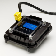 The Infinitybox MASTERCELL
 Copyright Infinitybox, LLC 2021. All Rights Reserved.
  Copyright Infinitybox, LLC 2021. All Rights Reserved.
  Copyright Infinitybox, LLC 2021. All Rights Reserved.
Trackbacks & Pingbacks
[…] encourage you to always use your configuration sheet to confirm wire colors in your specific kit. You can get more details on your configuration sheet by clicking this link. When you turn on your ignition switch, the POWERCELL will provide the key-on ignition power that […]
[…] Ed found the MASTERCELL input that corresponds to the OPEN output that he used. Your configuration sheet shows you which input and output wire colors go together. Ed connected this MASTERCELL input to […]
[…] Please note that this diagram does not give you the MASTERCELL input wire colors. You need to line up the function on the column to the wire color on your configuration sheet. Depending on your system and your accessories, you may have different wire colors for your inputs. Click on this link to learn more about your configuration sheet. […]
[…] Check the configuration sheet that came with your Infinitybox 20-Circuit for the correct wire colors for the inputs and outputs mentioned in this blog post. You can learn more about the configuration sheet at this link. […]
[…] to confirm that you have the correct input wired to the switch by following the details of your Configuration Sheet. You can also use this to confirm that you switch is working correctly and that you have good […]
[…] came with your kit will get you all of the details that you’d need to use these open outputs. This link will take you to a blog post that gives you more detail on how to read the configuration s…. All of the open outputs are set to TRACK. This means that the output will track the state of […]
[…] In the case of the fuel pump, there is a dedicated output on the rear POWERCELL. In the case of this 1967 Mustang Kit, this is the tan wire on the POWERCELL A output harness. That is output 10. The input wire to the MASTERCELL is number 19. This is the tan wire with the yellow tracer wire on the MASTERCELL B input harness. Check your configuration sheet for the specifics on the POWERCELL output wire and the MASTERCELL inp…. […]
[…] take you to the configuration sheet for the system that we are installing in this 1967 Mustang. This link will take you to our previous post in this series going through the details of the configu…. You will see that there are several outputs that are labeled as OPEN on the configuration sheet. […]
[…] first thing that we did was to check the configuration sheet for this system. You can get more details on the configuration sheet for your system by clicking this link. The MASTERCELL inputs for the headlights and parking lights are going to connect to the switch. […]
[…] by checking the configuration sheet that came with your kit. This link will take you to an earlier post in this series about the importance of your configuration…. This car is wired with separate brake light and turn signal outputs on the rear POWERCELL so […]
[…] Remember that your configuration sheet is your road map to wiring your car with our Infinitybox system. Your configuration sheet will identify the wires by color for each of the switches in your car. You can click on this post to get a refresher on your configuration sheet. […]
[…] If you need it, you can get more information on how to read our configuration sheets by clicking thi…. […]
[…] lights are on outputs 6 on the front and 6 on the rear POWERCELL. These are the yellow wires. Click here to read the blog post that talks about the configuration sheet. Run your parking light output wire to the the closest parking light on that side of the car, […]
[…] a dedicated output for the headlights. Check your configuration sheet for the exact wire color. This blog post will show you how to do this. In the case of our 1967 Mustang project, the POWERCELL output wire for the headlights is the […]
[…] to the loads in the car. Remember that your configuration sheet is your road map to do this. You can review our previous blog post about the configuration sheet as a refresher by clicking this …. The configuration sheet is going to identify the specific POWERCELL output wire by color for […]
Leave a Reply
Want to join the discussion?Feel free to contribute!