 Copyright 2026 Infinitybox, LLC. All Rights Reserved.
 Wiring the Cooling Fan with the IPM1 Kit
Table of Contents
- Overview
- Wiring a Thermostatic Switch
- Wiring the Cooling Fan Trigger from an ECU
- Adding a Bypass Switch
- Wiring the POWERCELL Output to the Cooling Fan
- Resources
Overview
Your Infinitybox IPM1 Kit makes it easy to control your cooling fan. The MASTERCELL NGX takes the trigger signal from your temperature switch or ECU. It sends a command over the CAN network to the front POWERCELL to turn the cooling fan on and off. The POWERCELL has the switching and fuse protection built in. This eliminates the need for an external relay and a separate fuse for your cooling fan circuit.
The POWERCELL also soft-starts the cooling fan motor. This reduces the in-rush current when the fan first turns on. Soft-starting lets you drive a larger fan with a smaller gauge of wire. Click here to learn more about the benefits of soft-starting.
There are two main ways to trigger your cooling fan with the MASTERCELL NGX. You can use a traditional thermostatic switch or you can use the trigger from your ECU. The MASTERCELL NGX accepts both ground-switched and high-side switched (12-volt) inputs. This gives you the flexibility to handle either type of trigger without adding external components.
Before you go any further, check the configuration sheet that came with your IPM1 Kit. Your configuration sheet is the single point of truth for the wire colors and connector locations in your system. It will tell you which MASTERCELL NGX input is assigned to your cooling fan and which POWERCELL output drives the fan motor.
Wiring a Thermostatic Switch
The most common way to trigger your cooling fan is with a thermostatic switch. This is a temperature-activated switch that is usually threaded into your radiator or your engine. Inside the switch, there is a bi-metal element that is set for a specific temperature. When the coolant temperature exceeds that set point, the switch closes internally and connects its terminal to ground. When the coolant temperature drops below the set point, the switch opens and disconnects from ground.
This is a ground-switched signal. You are going to connect the MASTERCELL NGX input for your cooling fan directly to the terminal on the thermostatic switch. When the switch closes, it will ground the MASTERCELL NGX input. The MASTERCELL NGX sees this change and sends a command to the front POWERCELL to turn on the cooling fan output. When the switch opens, the MASTERCELL NGX sends a command to turn the output off.
There are two common types of thermostatic switches. The most common type has a single quick-disconnect terminal. This type of switch grounds through its metal body when it threads into the radiator or the engine. You connect the MASTERCELL NGX input wire to that terminal.
The second type has two terminals. Both terminals are isolated from the metal body of the switch. You connect the MASTERCELL NGX input to one terminal and connect the other terminal to ground.
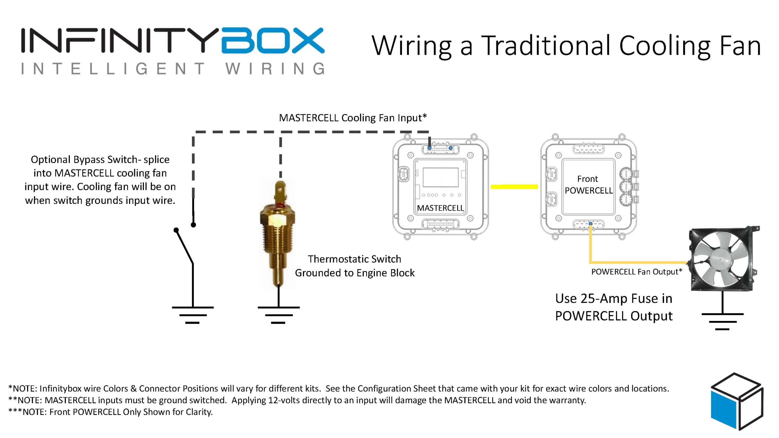
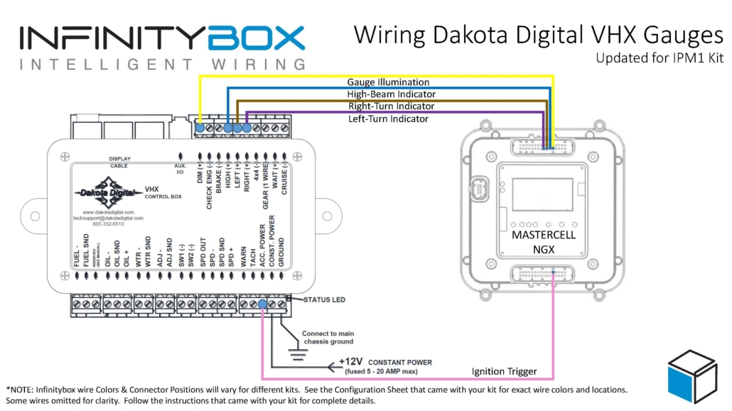
Image of wiring diagram showing how to wire a thermostatic cooling fan switch to the Infinitybox MASTERCELL
Here is an important note about temperature switches and temperature senders. There is a big difference between them. A temperature switch turns on and off at a set temperature. A temperature sender is a variable-resistance device that controls your temperature gauge. You cannot connect your cooling fan input on the MASTERCELL NGX to your temperature sender. They are two separate devices with two separate functions.
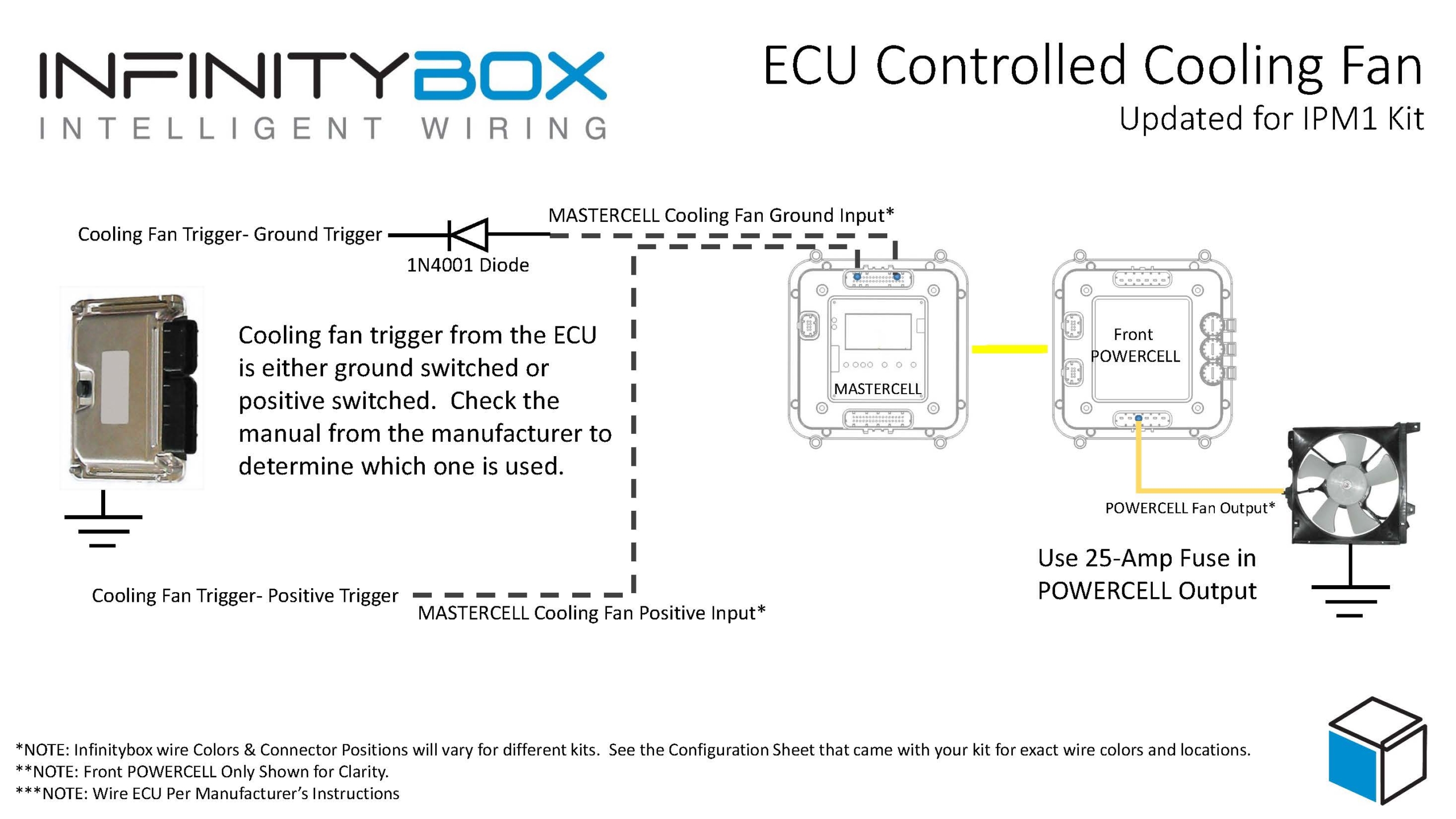
Wiring the Cooling Fan Trigger from an ECU
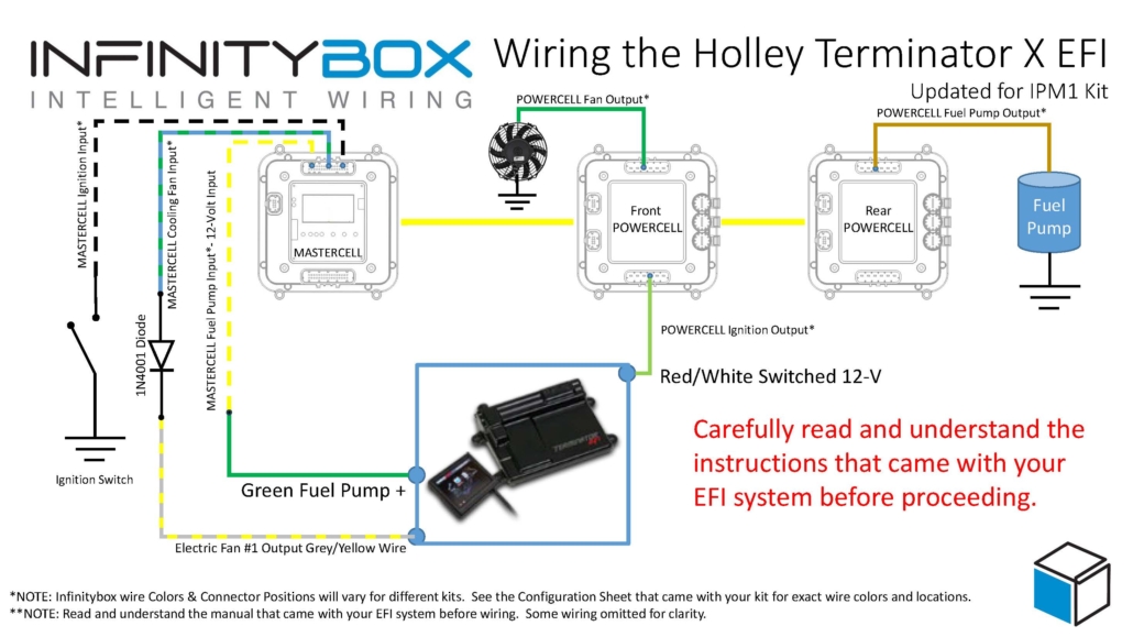
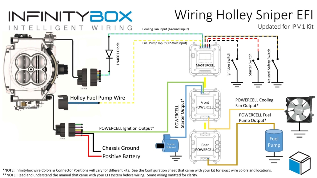
Many modern ECUs and EFI systems have a dedicated output to trigger the cooling fan. The ECU monitors the engine coolant temperature through its own sensor and decides when to turn the fan on and off. If your ECU has this capability, you can wire its cooling fan trigger directly to the MASTERCELL NGX instead of using a thermostatic switch.
The important thing to understand is whether your ECU has a ground-switched trigger or a 12-volt (high-side switched) trigger. Check the manual for your ECU to determine which type of trigger it has. The MASTERCELL NGX can handle both types of triggers natively.
This diagram shows the connections between the thermostatic cooling fan switch, the MASTERCELL NGX, and the front POWERCELL in the Infinitybox IPM1 Kit.
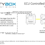
Ground-Switched Trigger from ECU
If your ECU has a ground-switched cooling fan trigger, it internally connects the trigger wire to ground when it wants the fan on. You are going to connect this trigger to a ground-switched input on the MASTERCELL NGX.
We always recommend isolating any ground-switched input from an external system like an ECU with a 1N4001 diode. The reason is that we do not know what the ECU does with its trigger when it is off. It may let the trigger voltage float or it may pull the trigger up to battery voltage. Either of these conditions could cause erratic behavior on the MASTERCELL NGX input. To isolate the input, solder a 1N4001 diode in series between the MASTERCELL NGX input and the cooling fan trigger wire on the ECU. Install the diode with the anode facing the MASTERCELL NGX. The orientation of this diode is critical and the system will not work correctly if the diode is wired backwards.
12-Volt Trigger from ECU
If your ECU has a 12-volt cooling fan trigger, it outputs battery voltage on the trigger wire when it wants the fan on. You are going to connect this trigger to one of the high-side switched inputs on the MASTERCELL NGX.
The MASTERCELL NGX has the ability to accept 12-volt input signals directly on its high-side switched inputs. There is no need for an inVERT Mini or any other external component to flip this signal. This is one of the key advantages of the MASTERCELL NGX in your IPM1 Kit.
Adding a Bypass Switch
You may want to add a bypass switch that lets you turn on the cooling fan manually at any time. This is usually a simple toggle switch on the dash. It gives you the ability to turn the fan on even when the engine is not up to temperature.
To wire a bypass switch, connect a MASTERCELL NGX ground-switched input to one terminal on the toggle switch. Connect the other terminal to ground. You can assign this to the same cooling fan output on the POWERCELL through your inCODE NGX configuration. When you flip the switch, it grounds the MASTERCELL NGX input and turns on the cooling fan regardless of the state of your thermostatic switch or ECU trigger.
Check your configuration sheet for the specific input assigned to your bypass switch.
Wiring the POWERCELL Output to the Cooling Fan
Once you have the trigger side wired to the MASTERCELL NGX, you need to wire the output side. Connect the cooling fan output on your front POWERCELL to one wire on the cooling fan motor. Connect the other wire on the cooling fan motor to a good chassis ground. Make sure you have a solid metal-to-metal connection with no paint, grease, powder coating, or dirt in the way.
We recommend using a 25-amp fuse in the POWERCELL output to protect the wiring between the POWERCELL and the fan motor. Check your configuration sheet for the specific output and wire color for your cooling fan.
Resources
Our resources section has wiring diagrams for many different ECU and EFI systems. These show the specific connections between the ECU and the MASTERCELL NGX for the cooling fan trigger, fuel pump trigger, and ignition power. Check the blog on our website for your specific ECU.
Click here to contact our team or call us at (847) 232-1991 with any questions about wiring your cooling fan with the IPM1 Kit.
 Copyright 2026 Infinitybox, LLC. All Rights Reserved.


 Copyright 2026 Infinitybox, LLC. All Rights Reserved.
 Copyright 2026 Infinitybox, LLC. All Rights Reserved.