Posts

Dakota Digital GSS-3000

This blog post will show you the connections that you need to make between your Infinitybox 20-Circuit Kit and the Dakota Digital GSS-3000 Universal Gear Shift Sender.  The GSS-3000 is designed to drive the gear selector indicators on your dash from any automatic transmission.  Their kit has a rotary potentiometer that connects to the shift linkage on the transmission.  It learns the position of the different gears and sends signals to indicators on your dash to show you what gear you are in.  It is a simple and clever product.  The Dakota Digital GSS-3000 has contacts that are designed to drive your back up lights when you have the transmission in reverse.  It also has a set of contacts for a Neutral Safety Switch.  This sends out a signal when the transmission is in park or neutral and it is safe to start the engine.  Your Infinitybox system can take in these two signals to easily drive your back up lights and manage your Neutral Safety Switch.  Keep reading to learn more.

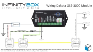
Before you go any further, it is important that you read and carefully understand the instructions for your Dakota Digital GSS-3000 Universal Gear Shift Sender.  You can download these instructions from their website by clicking here.  This blog post is only going to cover the ignition power to the GSS-3000, the neutral safety signal and the connection to the back up lights.  Please follow their instructions for the rest of the wiring to the module.  This picture will show the wiring diagram for the connections to the GSS-3000.

Picture of Infinitybox Wiring Diagram for the Dakota Digital GSS-3000

Picture of Infinitybox Wiring Diagram for the Dakota Digital GSS-3000

First, you need to provide key-on ignition power to the module.  When the key is in the run position, the module will get its power.  You’re going to tap into the ignition output on your front POWERCELL.  Check your configuration sheet for the wire color for your ignition output.  You can splice into this wire directly or you can use one of our Splice Saver Kits to make a simple and clean connection for ignition power.

Next, you can take their Back Up signal and use it to control the back up lights in the back of you car.  The advantage of doing it this way is that you’re running less wire.  The signal will come from the GSS-3000 in the front of the car and connect to the MASTERCELL, also in the front of the car.  The back up lights will get their power from the rear POWERCELL.  You are not running a wire all the way from the GSS-3000 in the front of the car to the back up lights in the rear of the car.  The GSS-3000 puts out a positive signal for the back up lights.  You need to use one of our inVERT Minis to flip this to a ground signal.  See the details in the wiring diagram for how to make these connections.

Lastly, you can use the Dakota Digital GSS-3000 to send the MASTERCELL the signal for the Neutral Safety Switch.  The MASTERCELL needs to see a ground signal through the input for the Neutral Safety Switch.  Check your configuration sheet for specifics on the wire color for your system.  This blog post will get you more details on the Neutral Safety Switch input.  In a lot of transmissions, there is a switch built into them that will give you this signal for when it is safe to start the engine.  If your transmission does not have a built-in safety switch, you can use the signal from the GSS-3000.  This is a ground signal from their SAFETY terminal.  We recommend wiring a 1N4001 diode in series with the MASTERCELL input to isolate the MASTERCELL from the GSS-3000.  This blog post will get you more details about wiring this diode in line.  When you have the transmission in the park or neutral position, the MATERCELL will get the signal that it safe to start the engine.

The is an important consideration here regarding using the GSS-3000 neutral safety signal and the Infinitybox built-in One-Button Start feature.  This feature will not work if you are taking the neutral safety signal from the GSS-3000.  Since the GSS-3000 is getting its power from the ignition output from your POWERCELL, the module will not trigger the neutral safety signal in time for the MASTERCELL to process this.  You will need to use an external neutral safety switch if you want to use our One-Button Start feature and the GSS-3000.

You can download a PDF version of this wiring diagram by clicking this link.

Our technical support team is always available to help you wire your car or truck with our Infinitybox system.  Click this link to contact our team with any questions.


Reverse Lockout Solenoid

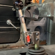
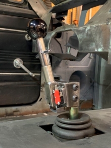
A customer just sent us pictures showing how he wired a switch into his transmission shifter to control his reverse lockout solenoid.  He wanted to make sure that he couldn’t accidentally shift into reverse when he was in the upper gears.  By using our Infinitybox wiring system, he was able to easily control this solenoid.

Ed K. is building a 1968 Pro-Touring Mustang fastback.  He has transplanted a Coyote engine from a 2014 Mustang and mated it to a Tremec T56 6 speed transmission, feeding a Ford 9 inch rear end for the drivetrain.  He is using our 20-Circuit Kit with inLINK, inRESERVE and inMOTION to wire his car.

The Tremec transmission is outfitted with a solenoid lockout feature that further pre-loads an already compressed spring acting on the shift gate to prevent accidentally engaging reverse while downshifting from 6th gear to 5th gear, which would be catastrophic. In order to engage reverse, when desired, this solenoid must be energized to remove this extra spring pre-load. Typically, this solenoid is energized by a body controller when the car is moving at 5 miles per hour or less to allow a shift into reverse. Ed wanted a simpler way to engage this reverse lockout solenoid in his 1968 Mustang.

Ed modified the shift lever to add a microswitch to it.  When he pulls up on the shifter handle, the switch closes.  He can use this switch to control his reverse lockout solenoid.

Ed picked the OPEN output on his front POWERCELL to power his reverse lockout solenoid.  The OPEN outputs on your configuration sheet can be used for practically anything.  They are auxiliary outputs for any additional electrical accessories that you may have on your car.  Click on this link to learn more about OPEN outputs.

Ed connected this open POWERCELL output wire to the solenoid, then grounded the other side of the solenoid wiring.

Next, Ed found the MASTERCELL input that corresponds to the OPEN output that he used.  Your configuration sheet shows you which input and output wire colors go together.  Ed connected this MASTERCELL input to the normally open terminal on his shifter switch.  Then he connected the common terminal of the switch to ground.  When he pulls up on the reverse handle, the switch closes.  This connects the MASTERCELL input to ground.  The MASTERCELL sends a command to the front POWERCELL to turn on the output, which energizes the reverse lockout solenoid.  This pulls back the reverse gate, which lets him shift into reverse.  Here is a simple wiring diagram showing how this was connected.

Picture of simple schematic showing how to control a reverse lockout solenoid with the Infinitybox system.

Picture of simple schematic showing how to control a reverse lockout solenoid with the Infinitybox system.

Ed was able to wire his reverse lockout solenoid easily with our Infinitybox system.  He didn’t have to add any relays to his car to do this.  He was able to use the flexibility and expandability of our system to get what he needed in his car.

You can download a PDF version of this wiring diagram by clicking this link.

Click on this link to learn more about what the Infinitybox system can do for your restoration, street rod, resto-mod, kit car or pro-touring build.


AM Equipment Windshield Wiper Motor

Wipers

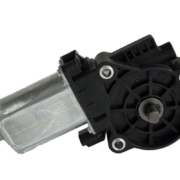
We get a lot of questions about wiring windshield wipers and washer pumps with our Infinitybox system.  There can be a lot of complexity with windshield wiper kits because of the functions that need to be managed.  There are multiple speeds, which are usually different windings on the wiper motor.  There can be intermittent features, which can be controlled by a separate module or by electronics in the switch.  There is the park function that is usually controlled mechanically by a cam inside the wiper motor.  To compound the complexity, different OEMs managed wipers differently.  To make wiring your windshield wipers as easy as possible, we encourage you to think of the switch, the motor and the washer pump as a single system.  You are going to power this single system from your Infinitybox system and let the switch manage the windshield wiper functions.

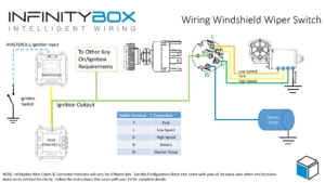
Almost all aftermarket wiper systems work the same way.  They include a wiper motor with two separate windings for low and high-speed.  The motor also includes a wire that manages the park position of the wipers.  These systems may include a washer pump that needs 12-volts to spray windshield solvent on to the window.  Lastly, they include a switch that turns on the different speeds, controls the washer pump and controls the park.  In general, all of these wiper systems wire the same way.  This post is going to look at a universal wiper system.  Please read the instructions that came with your kit and contact us if yours looks different.  This diagram shows a universal wiring schematic for a windshield wiper kit.

Picture of a wiring diagram showing how to wire a windshield wiper switch to the Infinitybox system.

Picture of a wiring diagram showing how to wire a windshield wiper switch to the Infinitybox system.

As we mentioned above, you need to think of this kit as a full system.  You are going to power it and let it control itself.

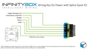
Your wiper switch is designed to take in power from the battery and route that to the different terminals on the wiper motor and the washer pump.  To start, there should be a terminal on the switch that connects to ignition or key-on power.  In most cases, it is identified with a “B” for battery.  You are going to connect this “B” terminal to your POWERCELL ignition output.  In most kits, this is the light-green wire on your front POWERCELL but check your specific configuration sheet.  You are going to tap into your ignition output to get this power for the wiper switch.  You can simply splice into the ignition output wire or you can use our Splice Saver to create an ignition buss bar.  Check out this picture to see how you would use the Splice Saver to get your ignition power for your wiper switch.

Wiring ignition key-on power with the Infinitybox Splice Saver Kit

Wiring ignition key-on power with the Infinitybox Splice Saver Kit

By using the ignition output on your POWERCELL, your wiper switch will have power when you key is in the ON position.  You wipers will not work when the ignition is off.  You can also use one of the OPEN outputs in your kit to create an accessory buss bar that would be separate from your ignition output.  Click on this link for more details on creating a separate accessory buss.  

Once you have the power wired to your wiper switch, follow their instructions for making the connections from the switch to the wiper motor and the washer pump.  There are usually connections for the low-speed and high speed windings plus the washer pump.  When you turn the switch to the low-speed position, the switch takes ignition power and directs that to the low-speed windings on the motor.  It does the same for the high-speed.  When you push in on the switch, it sends ignition power to the washer pump.

When you turn the switch off, it puts ignition power on the park wire that goes to the motor.  The wiper motor has a cam inside its mechanism that routes power to the low-speed windings until the wipers return to the park position.  When they get home, the cam in the mechanism opens a switch that stops the motion of the wipers.

You can download a PDF version of the wiper switch wiring diagram by clicking this link.

Give our team a call at (847) 232-1991 if you have any questions about powering your windshield wipers with our Infinitybox system.  You can also contact our team directly by clicking this link.

Floor dimmer switch

Floor Mounted Dimmer Switch

When it comes to controlling lights with our Infinitybox system, you have many different options.  This is especially true for your headlights and high-beams.  You can see earlier blog posts about wiring headlights and high-beams by clicking these links.  In most cases, you are going to use the headlight and high-beam outputs on the front POWERCELL.  These are controlled by their own inputs connected to different switches on your dash or the steering column.  You can also use a floor-mounted headlight dimmer switch to switch between the headlights and high-beams in your car.  This blog post will show you the details.

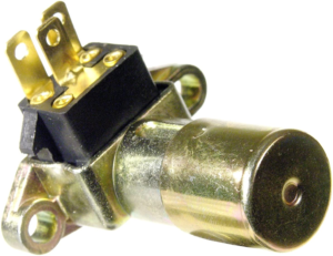
The floor dimmer switch is designed to toggle between the headlights and high-beams.  The headlight switch brought power to a common terminal on the switch.  The headlights and the high-beams wired to their respective output terminals on the switch.  When you turn on the headlight switch, power is applied to the dimmer switch on the floor.  Pressing this switch with your foot toggles between the headlights and high-beams.  When you turn off the headlight switch, there is no power at the switch so your headlights and high-beams turn off.

Floor dimmer switch

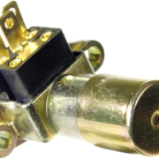
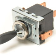
Picture of a floor headlight dimmer switch

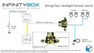
Wiring a floor dimmer switch is simple with the Infinitybox system.  First, you are going to wire your headlight switch to the headlight input going to the MASTERCELL.  Remember that the MASTERCELL inputs are ground switched.  When the headlight input is switched to ground, the MASTERCELL will tell the front POWERCELL to turn on the output for the headlights.  We have many different wiring diagrams showing different how to wire different headlight switches in the Resources section of our website.  This link will take you to the wiring details for the most common GM-style headlight switch.

If you are going to use a dimmer switch on floor to switch between headlights and high-beams, you will not need to use the high-beam output on your front POWERCELL.  This opens up this output to be used for other accessories or auxiliary functions.

Next, you are going to connect the headlight output from your front POWERCELL to the common terminal on your dimmer switch.  In most cases, this is the center terminal on the switch.  It may also be labeled as “From Headlight Switch”.  Check the wiring diagram for your specific switch.

Next, you are going to connect the output terminals from your dimmer switch to your headlight bulbs and high-beam bulbs.  The terminals on your switch should be labeled for the headlights and high-beams.  Check the wiring diagram for your specific switch for more details.

Lastly, you can tap off the high-beam terminal on the dimmer switch with a wire for the high-beam indicator on your dash.

This wiring diagram shows the connection from the MASTERCELL to the headlight switch, the headlight output from the POWERCELL to the dimmer switch, the connections from the dimmer switch to the headlights & high-beams and the connection for the high-beam indicator on the dash.

Floor dimmer switch wiring diagram image

Picture showing wiring diagram for a floor mounted headlight dimmer switch.

You can download a PDF version of this wiring diagram by clicking this link.

Reach out to our team if you have any questions about wiring a floor dimmer switch to control your headlights and high-beams with the Infinitybox system.  You can call us at (847) 232-1991 or click on this link to contact our team directly.

Wiring Switches in Parallel

Our Infinitybox system is the most powerful and flexible wiring harness available in the market. Our MASTERCELL inputs are flexible and adaptable for practically any application. A customer just asked this question and we thought that it was a great way to show off the flexibility of the MASTERCELL inputs. The customer is wiring the power window switches in his car. He wanted to know if there was a way to wire a parallel switch that would control all 4 windows at the same time. The answer is “yes” and this blog post will show you how to do it.

Our MASTERCELL inputs work by getting connected to ground. This link will take you to an older blog post that goes through the details of how the inputs work and how to connect a switch to them. Since the inputs work by a ground trigger, this gives you a lot of flexibility with your switches.

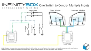
This picture shows you how to wire in a parallel switch to control multiple inputs simultaneously.

Picture of a wiring diagram showing how to wire two Infinitybox MASTERCELL inputs in parallel

Picture of a wiring diagram showing how to wire two Infinitybox MASTERCELL inputs in parallel

In this example, we’re showing two switches that control the driver’s and passenger’s windows. For the sake of clarity, we’re only showing the front windows and we’re only showing the down action. These switches are labeled Driver Down and Passenger Down in the wiring diagram. You are going to follow the wire colors from your configuration sheet to wire the switches and the power wires that go to the window regulator motors.

To wire in the parallel “master” switch, you are going to connect the MASTERCELL inputs for the Driver’s and Passenger’s switch together and bring them to the parallel switch. The important thing here is that you need to put a diode on each of the wires from the Driver’s and Passenger’s switch. These diodes are electrical check valves. They only let current flow in one direction. They block the flow of current in the other direction. Without these diodes, both the MASTERCELL inputs would be connected together at the parallel switch. They would both turn on with either switch. The diodes electrically isolate the two MASTERCELL inputs so they are operate independently from the individual switches but work together from the parallel switch.

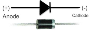
You can source these diodes anywhere. We recommend a 1N4001 diode. These can be purchased easily from Amazon or other on-line retailers. The orientation of the diodes critical. This will not work correctly if they are installed backwards. Note the orientation of the diode symbol in the wiring diagram above. The line on the diode symbol corresponds to the silver line on the case of the diode. Look at the picture below.

Example of a simple diode

Example of a simple diode

We only show the down action for the power windows in this diagram. We also only show 2 window switches. You can join all 4 inputs together through diodes if you want to control your front and rear windows from a single parallel switch. You can also repeat this for the up action of your power windows.

This same approach can be used for other switches like your lighting. We posted a wiring diagram a while ago showing you how to wire your head lights and parking lights from a single switch using a similar arrangement. You can view that blog post by clicking this link.

Click on this link to download a PDF version of this wiring diagram.

Click on this link to contact our technical support team with any additional questions about wiring your car or truck with our Infinitybox system.


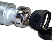
Picture of keyed ignition & starter switch

Wiring an Ignition Switch

We’ve been helping guys wire their cars for over 10 years. Sometimes we find ourselves skipping over the basics of how our Infinitybox system works and the advantages that it has over traditional wiring harnesses. A customer called us today with questions about wiring an ignition switch to his MASTERCELL. We were surprised to see that we didn’t have a good wiring diagram nor blog post talking about this. This post will correct that.

The MASTERCELL inputs on an Infinitybox system work by getting connected to ground instead of connecting to battery voltage. This has a bunch of advantages over a traditional wiring harness.

First, the MASTERCELL inputs are just triggers to the system. All of the current is carried by the POWERCELLs. Very little current is required at the MASTERCELL. This means that you can use practically any switch to turn on an input to the MASTERCELL.

Second, since practically no current is required at the switch, the MASTERCELL input wires can be very thin. Our standard input harnesses use 22-AWG wire. This keeps the bulk of the harnessing behind your dash to a minimum.

Lastly, you can easily combine MASTERCELL inputs to a single switch to get more advanced functions without having to change anything in the software.

Click on this link to learn more about how the MASTERCELL inputs work.

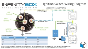
The ignition switch on your car is probably the most important thing. It lets you start and stop the engine. Most ignition switches work the same way. They all have terminals for power, ignition and starter. Some have an additional terminal for powering accessories. This wiring diagram shows how to connect your MASTERCELL inputs to a typical ignition switch.

Image of wiring diagram showing how to wire an ignition switch with the Infinitybox system.

Image of wiring diagram showing how to wire an ignition switch with the Infinitybox system.

As mentioned above, the MASTERCELL inputs work by getting connected to ground. To do this, you are going essentially wire the switch backwards. Instead of connecting the switch to power, you are going to connect it to ground. The first thing to do is connect the battery terminal on the switch to ground. Most switches label this terminal as BAT. Others will label this terminal as B+ or +12V. Look closely at the labels near the terminals to identify the battery terminal. You can either ground this terminal directly to the chassis or you can use one of the black ground wires that is included in the MASTERCELL inputs harness. This ground connection is critical. See our previous posts about how to get good ground connections.

Next, you need to connect the MASTERCELL inputs to the terminals for Ignition and Starter. When the key is in the Ignition position, you need to have power for all of things that run your engine. These include your engine management system, your coils, your gauges and your dash. These are all powered from the Ignition output on your POWERCELL. There is a corresponding MASTERCELL input that turns on this output. Check your configuration sheet to identify these wire colors. Once you know the MASTERCELL input for your Ignition, connect that to the Ignition terminal on the switch. This terminal may be marked as IGN. It could also be marked as RUN. There is an easy way to identify the correct terminal for the Ignition. Turn the key to the Ignition or Run position and measure continuity between the BAT terminal and the IGN terminal. You should have continuity in the run position. It should be open circuit when the key is off.

For the starter input, check your configuration sheet to identify the wire color for the starter. Connect this wire to the ST terminal on your switch.

Lastly, some switches may have an Accessory position on them. This terminal lets you control outputs independently from the ignition. For example, some customers want to be able to power their stereo separately from the ignition so they may listen to music without running their EFI system. The Accessory wires the same way as the ignition and starter. Simply choose an OPEN auxiliary output from your configuration sheet ans connect the corresponding MASTERCELL input to the ACC terminal on the switch. Note that most accessory positions on ignition switches are on in the ACC and IGN positions but off in the START position.

You can download a PDF version of our wiring diagram showing how to wire an ignition switch by clicking this link.

Click this link to contact our technical support team with any additional questions about wiring your car or truck with our Infinitybox system.

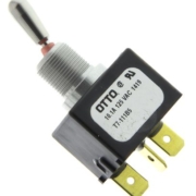
Example of a SPDT Switch

Headlights with SPDT Switch

A customer emailed us to ask how he could control his parking lights, headlights and high-beams from a single switch on his dash.  He wanted to use a toggle switch with three positions: down for head lights, up for high-beams and off in the center.  When either the headlights or high-beams were on, he wants his parking lights on.  This is really easy to do with our Infinitybox system.  Check out the details below to see how easy it is to wire your headlights with a SPDT switch.

There are many different types of toggle switches.  The major categories are sorted into the number of positions or throws of the switch and the number of poles or contacts.  A single throw switch was two positions.  These are designated as single throw or ST.  A three position switch has two throws from the center position: one up and one down.  These are designated as DT for double throw switches.

The number of poles on a switch designates the number of contacts.  The most common is single pole.  This means that each position on the switch is connected back to a common point with a single terminal.  These are designated as SP switches for single pole.  The more complicated switch is double pole.  These have two terminals for each position or throw of the switch.   This link will take you to a good Wikipedia article that talks about switches in more detail.

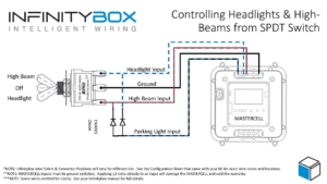
For this application, our customer needs a SPDT switch.  This is a single pole, double throw switch.  The switch has three positions: off in the center and on in the up and down positions.  It has a single pole for each position.  This diagram will show you how to wire MASTERCELL inputs to control the headlights and high-beams off of this Single Pole, Double Throw Switch.

Picture of a wiring diagram showing how to wire a SPDT switch to control headlights, parking lights and high-beams with the Infinitybox system

Picture of a wiring diagram showing how to wire a SPDT switch to control headlights, parking lights and high-beams with the Infinitybox system

The MASTERCELL input for the headlights connects to the top terminal of the switch.  The input for the high-beams connects to the bottom terminal of the switch.  The middle or common terminal of the switch needs to get connected to ground.  This can go to the chassis or can connect to one of the black ground wires in the MASTERCELL input harness.

When the switch is in the middle position, nothing is connected so the headlights and high-beams are off.  When you flip the switch to the down position, the input for the headlights gets connected to the center terminal, which is ground.  This triggers the headlight input on the MASTERCELL.  To turn on the high-beams, you flip the switch to the up position.

For your parking light input, you need to wire this to both the headlight and high-beam contacts on the switch but there is an important step that you need to follow.  If you were to just wire the parking light input to the headlight and high-beam terminals on the switch, all of the inputs would be electrically connected together.  All three outputs would turn on at the same time in either the headlight or high-beam position.  You need to isolate the headlights and high-beams with diodes for this to work properly.  You need to connect the MASTERCELL input for the parking lights to the headlight and high-beam terminals through two diodes.  These diodes should be a 1N4001 rectifier and these can easily be purchased from Amazon.  The diodes act like one-way check valves.  They do not let the parking light input connect between the headlight and high-beam input.  The orientation of these diodes are very important.  If they are wired backwards, this will not work.  Please look at the wiring diagram for proper orientation of these diodes.

When the switch is flipped to the headlight position, the parking light input gets connected to ground through the diode.  The same thing happens when the switch is in the high-beam position.  The parking lights will turn on when the switch is in the headlight of high-beam position if you follow this wiring diagram.

You can download a PDF copy of this wiring diagram by clicking this link.

If you have questions about this wiring diagram or need specific help wiring your car with our Infinitybox system, click on this link to contact our technical support group.

Picture of a Lucas Headlight Switch

Lucas Switch

There are very few companies in the car world that get the ribbing of Lucas Industries.  They are the butt of many an old car guy’s jokes about reliably, safety and burning.  The company was founded in the 1860’s in the UK and produced electrical components for over 100 years for all of the popular British brands.  These include MG, Austin, Cooper, Jaguar and even the ubiquitous Cobras built by Shelby.  It is not uncommon to hear of them referred to as “Lucifer” because of their alleged history of causing vehicle fires.  One of the benefits of our Infinitybox system is that you can use practically any switch to control things in your car.  This includes a period correct Lucas switch in your restoration of a MG or a Cobra replica build.  Read below how to connect the Lucas 31788 headlight switch into the inputs on your Infinitybox MASTERCELL.

Our Infinitybox system has been used to wire some of the most advanced resto-mods and Pro-Touring builds.  At the same time, our customers use our system in a lot of classic restorations and component car builds.  The most popular component car that we see from our customers is the MK4 Roadster from Factory Five.  This is a great replica of the Cobra made famous by Carroll Shelby.  A lot of guys want to build this car and customize it to make it unique to them.  Other guys want to build it period correct to look like the original Cobras but with all modern systems under the skin.

We got a question this week from one of our customers building a Factory Five Cobra.  He wants to use the original headlight switch from Lucas in the car and wanted to know how to wire it to the MASTERCELL inputs.  He’s using the Lucas 31788 switch.  That’s an easy thing to do.

One of the advantages of our system is that it takes very little current to turn on a MASTERCELL input.  The actual amount is less than 1 milli-amp.  (0.001 Amperes).  This means that you don’t have to use high-current switches to turn your lights, fans, ignition or starter solenoid on or off.  The high-current part of the circuit is managed in the POWERCELL.  A lot of the alleged issues that Lucas had over the years came from too much current being pushed through their switches.  Our MASTERCELL completely eliminates that.

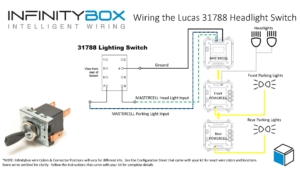
This diagram shows you the specifics on how to wire the MASTERCELL inputs for parking lights and head lights to the Lucas switch.

Picture of Infinitybox wiring diagram showing how to control headlights and parking lights from a Lucas Switch

Picture of Infinitybox wiring diagram showing how to control headlights and parking lights from a Lucas Switch

Terminal 4 on the switch needs to get connected to ground.  If you understand how the switch works, this may seem counter-intuitive, just trust us.  You can either connect this terminal directly to the chassis or use one of the black ground wires that is included in the MASTERCELL inputs harness.  Using one of the dedicated ground wires is our preferred way of wiring these kinds of switches.

From there, connect the MASTERCELL input for the parking lights to terminal 7 and the input for the head lights to terminal 8.  The switch is set up internally so that the parking lights will stay connected when the switch is in the headlight position.

Check the specific configuration sheet that came with your kit for the exact wire colors and connector locations for these inputs.  Different configurations may have different wire colors and connector locations.

You can read these blog posts to get more details about wiring the head lights and parking lights to the POWERCELL outputs.

That’s all you need to do to wire your headlights and parking lights to this Lucas switch.  When you turn on the parking lights or the headlights, the MASTERCELL will see the switch turn on and send the appropriate commands to the front & rear POWERCELLs to manage the lights.

You can download a PDF copy of this wiring diagram by clicking this link.  If you have any other specific technical questions, you can contact one of our technical support engineers by clicking this link.


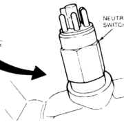
Sketch of the Reverse/Neutral Safety Switch Connector on a Ford AOD Transmission

Neutral Safety

A lot of people have seen a video from one of our customers starting his car remotely with an iPad.  His iPad is connected to the inTOUCH NET module in his car.  This lets him control everything including lights, windows, heat & A/C and locks.  It also lets him start the car.  Starting a car remotely can be very dangerous.  If the car is started with the transmission in gear, it can launch the car forward potentially injuring, maiming or killing someone.  In our Infinitybox system, there is a neutral safety switch input that must be wired before the engine will start.  This is true for starting it with a keyed switch, our one-button start or remotely from inTOUCH NET.

Some people call these park-safety switches, clutch interlock switches or neutral safety switches.  Regardless of what you call them, they are used to detect if it is safe to turn the starter.  They either detect that the transmission is in park, the transmission is in neutral, the clutch pedal is depressed or your foot is on the brake.  This is a standard input on all of our systems that must be wired correctly for the starter output to turn on.

The neutral safety input works like any other MASTERCELL input.  It must be connected to ground to work.  When you try to start the car, the MASTERCELL checks the state of the neutral safety input.  If it is not grounded, the MASTERCELL will not let the POWERCELL turn on the starter output.  The MASTERCELL must also see the neutral safety input change periodically.  If the input is tied directly to ground or if the switch fails, it will not let the starter crank.

All safety switches essentially work the same way.  If there is continuity through the switch then it is safe to start the engine.  Most transmissions have switches built into them that close when it is in neutral or park.  That is the case for our customer’s 1967 Mustang.  They are using a Ford AOD transmission with the built in switch.  In other cases, you may have a switch on your clutch pedal.  When you press the clutch, this closes the switch.  You wire the MASTERCELL input to one side of the switch and ground the other side.  You can also have a switch built into your shifter.  This switch is closed when the selector is in the park or neutral position.

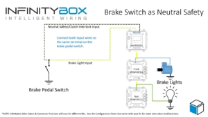
If your car has none of the options above, you can wire your neutral safety input from the MASTERCELL to the brake pedal switch in parallel with your brake light input.  When you step on the pedal, the MASTERCELL will see both the brake light input and the neutral safety input.  The brake lights will turn on and the MASTERCELL will allow the starter to crank.  You simply connect both MASTERCELL inputs to the same terminal on the brake pedal switch.  This diagram will show you how to do this.

Image of wiring diagram showing how to use your brake pedal as a neutral safety switch

Image of wiring diagram showing how to use your brake pedal as a neutral safety switch

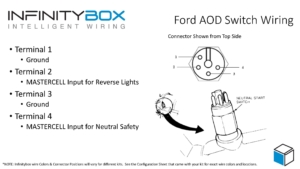
Going back to the Ford AOD transmission, there is a connector on the transmission for both the neutral safety and the reverse lights.  We’ll talk about reverse lights in an upcoming post.  This picture shows how to wire the MASTERCELL input for the neutral safety to the connector on the transmission.

Wiring diagram for Reverse/Neutral Safety switch on Ford AOD transmission

Wiring diagram for Reverse/Neutral Safety switch on Ford AOD transmission

The neutral safety input from the MASTERCELL will connect to Terminal 2 on the connector.  Terminal 1 will connect to ground.  See our warnings in previous posts about good ground connections.  When the transmission is in park or neutral, the switch closes.  This connects the MASTERCELL input to ground.  You can download a PDF of this wiring diagram by clicking this link.

Starting issues related to the neutral safety switch are probably our number 1 technical support call.  Most guys just don’t read this in the manual.  Your call will not start unless you have this MASTERCELL input wired properly.  Please click on this link to contact our technical support team with questions.

Ignition and Starter

Here’s the next step in wiring this 1967 Mustang.  In previous posts, we described wiring the ignition and starter outputs from the front POWERCELL.  You can get the Ignition output post at this link.  This link will take you to the starter output post.  In this post, we are going to describe the process of wiring the ignition and starter switch to the MASTERCELL inputs.

Our customer is using a steering column from IDIDIT for this Mustang.  They chose the option to have the keyed ignition and starter switch built into the column.  When you order this option from IDIDIT, you get a separate harness to connect from the column.  This link will take you to the instructions for this switch from IDIDIT.  Essentially, there are 4 wires in this harness.  These will connect to the MASTERCELL input wires.

Remember how our MASTERCELL inputs work.  You connect the input wire to one side of your switch.  The other side of the switch connects to ground.  When you turn the switch on, the MASTERCELL input gets connected to ground.  The MASTERCELL sees the input go to ground and sends a command to one of the POWERCELLs to do something.  In most cases when you are wiring OEM switches to a MASTERCELL, you will ground the battery feed and connect the input wires correspondingly.  This IDIDIT switch is no exception.

Here’s what you are going to do with the 4 wires in the switch harness.

First, you are going to connect the red wire to ground.  You can use any of the black wires in the MASTERCELL input harness or you can connect this directly to the chassis.  We’ve said this over and over, make sure that you have a good metal-to-metal connection between the ground wire and the chassis.  No paint, powder coating, rust, oil, grease, etc.  You want a good clean connection.

Next, you are going to connect the purple wire in the IDIDIT harness to the MASTERCELL input wire for the starter.  Check your configuration sheet.  Different configurations may have different wire colors for the starter.  In our configuration, the starter input wire is the white wire with the yellow tracer on the MASTERCELL A harness.  This is input number 4.  You can crimp, splice, solder or use connectors to make this connection.  See our earlier blog posts about connection techniques.

Next, connect the pink wire in the IDIDIT harness to the MASTERCELL input wire for the Ignition.  Same warning as above.  Check your configuration sheet for the exact wire color.  In our configuration, this is the white wire with the blue tracer on the MASTERCELL A harness.  That is input 3.

You will notice that this ignition and starter switch has an accessory position.  Some customers will use the accessory position on their switch to control an output that is different from their ignition output.  They may want to have their stereo on without having their ignition on.  In most configurations, there is an OPEN output on the front POWERCELL designed for this accessory function.  In our configuration, this is output 8.  It is controlled by input 8 on the MASTERCELL A connector.  That is the blue wire with the light-blue tracer.  We’re going to connect this wire to the brown wire in the IDIDIT harness.

Here’s how the different positions on the switch work.  When the key is in the accessory position, your accessory output on your POWERCELL will be on.  In the ignition or ON position, the ignition output will turn on.  So will the accessory output.  When you turn the key to the start position, the accessory will turn off.  The ignition will remain on and the starter output will turn on.

That’s all that it takes to connect the IDIDIT ignition and starter switch to the MASTERCELL in this 1967 Mustang.  We have a large collection of different ignition and starter switch wiring diagrams in our reference library on our website.  Click this link to get there.

Contact us if you have questions about wiring your ignition and starter switch to your 20-Circuit Kit.  Click on this link to contact one of our technical support engineers.