Ignition and Starter
Here’s the next step in wiring this 1967 Mustang. In previous posts, we described wiring the ignition and starter outputs from the front POWERCELL. You can get the Ignition output post at this link. This link will take you to the starter output post. In this post, we are going to describe the process of wiring the ignition and starter switch to the MASTERCELL inputs.
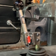
Our customer is using a steering column from IDIDIT for this Mustang. They chose the option to have the keyed ignition and starter switch built into the column. When you order this option from IDIDIT, you get a separate harness to connect from the column. This link will take you to the instructions for this switch from IDIDIT. Essentially, there are 4 wires in this harness. These will connect to the MASTERCELL input wires.
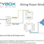
Remember how our MASTERCELL inputs work. You connect the input wire to one side of your switch. The other side of the switch connects to ground. When you turn the switch on, the MASTERCELL input gets connected to ground. The MASTERCELL sees the input go to ground and sends a command to one of the POWERCELLs to do something. In most cases when you are wiring OEM switches to a MASTERCELL, you will ground the battery feed and connect the input wires correspondingly. This IDIDIT switch is no exception.
Here’s what you are going to do with the 4 wires in the switch harness.
First, you are going to connect the red wire to ground. You can use any of the black wires in the MASTERCELL input harness or you can connect this directly to the chassis. We’ve said this over and over, make sure that you have a good metal-to-metal connection between the ground wire and the chassis. No paint, powder coating, rust, oil, grease, etc. You want a good clean connection.
Next, you are going to connect the purple wire in the IDIDIT harness to the MASTERCELL input wire for the starter. Check your configuration sheet. Different configurations may have different wire colors for the starter. In our configuration, the starter input wire is the white wire with the yellow tracer on the MASTERCELL A harness. This is input number 4. You can crimp, splice, solder or use connectors to make this connection. See our earlier blog posts about connection techniques.
Next, connect the pink wire in the IDIDIT harness to the MASTERCELL input wire for the Ignition. Same warning as above. Check your configuration sheet for the exact wire color. In our configuration, this is the white wire with the blue tracer on the MASTERCELL A harness. That is input 3.
You will notice that this ignition and starter switch has an accessory position. Some customers will use the accessory position on their switch to control an output that is different from their ignition output. They may want to have their stereo on without having their ignition on. In most configurations, there is an OPEN output on the front POWERCELL designed for this accessory function. In our configuration, this is output 8. It is controlled by input 8 on the MASTERCELL A connector. That is the blue wire with the light-blue tracer. We’re going to connect this wire to the brown wire in the IDIDIT harness.
Here’s how the different positions on the switch work. When the key is in the accessory position, your accessory output on your POWERCELL will be on. In the ignition or ON position, the ignition output will turn on. So will the accessory output. When you turn the key to the start position, the accessory will turn off. The ignition will remain on and the starter output will turn on.
That’s all that it takes to connect the IDIDIT ignition and starter switch to the MASTERCELL in this 1967 Mustang. We have a large collection of different ignition and starter switch wiring diagrams in our reference library on our website. Click this link to get there.
Contact us if you have questions about wiring your ignition and starter switch to your 20-Circuit Kit. Click on this link to contact one of our technical support engineers.

 Copyright Infinitybox, LLC 2021. All Rights Reserved.
  Copyright Infinitybox, LLC 2021. All Rights Reserved.
  Copyright Infinitybox, LLC 2021. All Rights Reserved.
 Copyright Infinitybox, LLC 2021. All Rights Reserved.
  Copyright Infinitybox 2022. All Rights Reserved.
  Copyright 2022 Infinitybox, LLC. All Rights Reserved.
  Copyright Infinitybox, LLC 2021. All Rights Reserved.


Leave a Reply
Want to join the discussion?Feel free to contribute!