 Image used courtesy of Holley Performance Products, Inc.
 Wiring the Holley HP EFI System
This blog post goes through the details of wiring the Holley HP EFI System with our Infinitybox 20-Circuit Kit. We will show you the ease and simplicity of wiring your EFI system with Infinitybox. The wiring is simple and short and you can eliminate the need for external relays. We’ll go through the key steps and give you a wiring diagram that shows you all the details to wire your Holley HP EFI Engine Management System with our Infinitybox system.
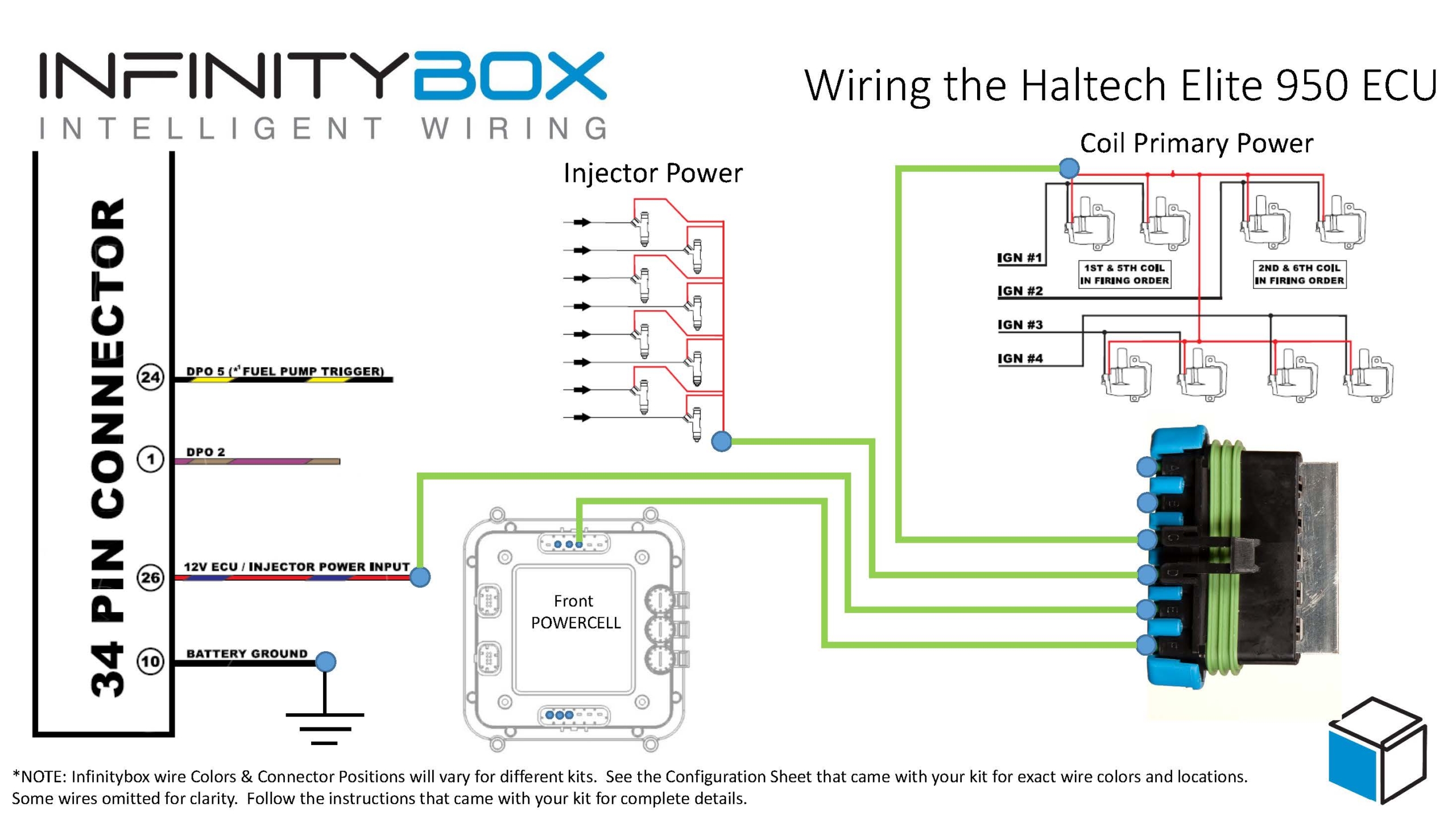
Before we get too far, you must thoroughly read and understand the instructions that came from Holley to install the HP EFI system. Please consult their website to get the instillation instructions. The other important thing to consider here is that we are going to show you how to connect your Infinitybox wiring system to the Holley HP. This will include wiring the key-on ignition power, the cooling fan trigger and the fuel pump trigger. Consult the Holley manual for all details regarding primary power from the battery, coil wiring, injector wiring, sensor wiring and grounds. This diagram shows you the connections between your Infinitybox system and the Holley HP ECU.
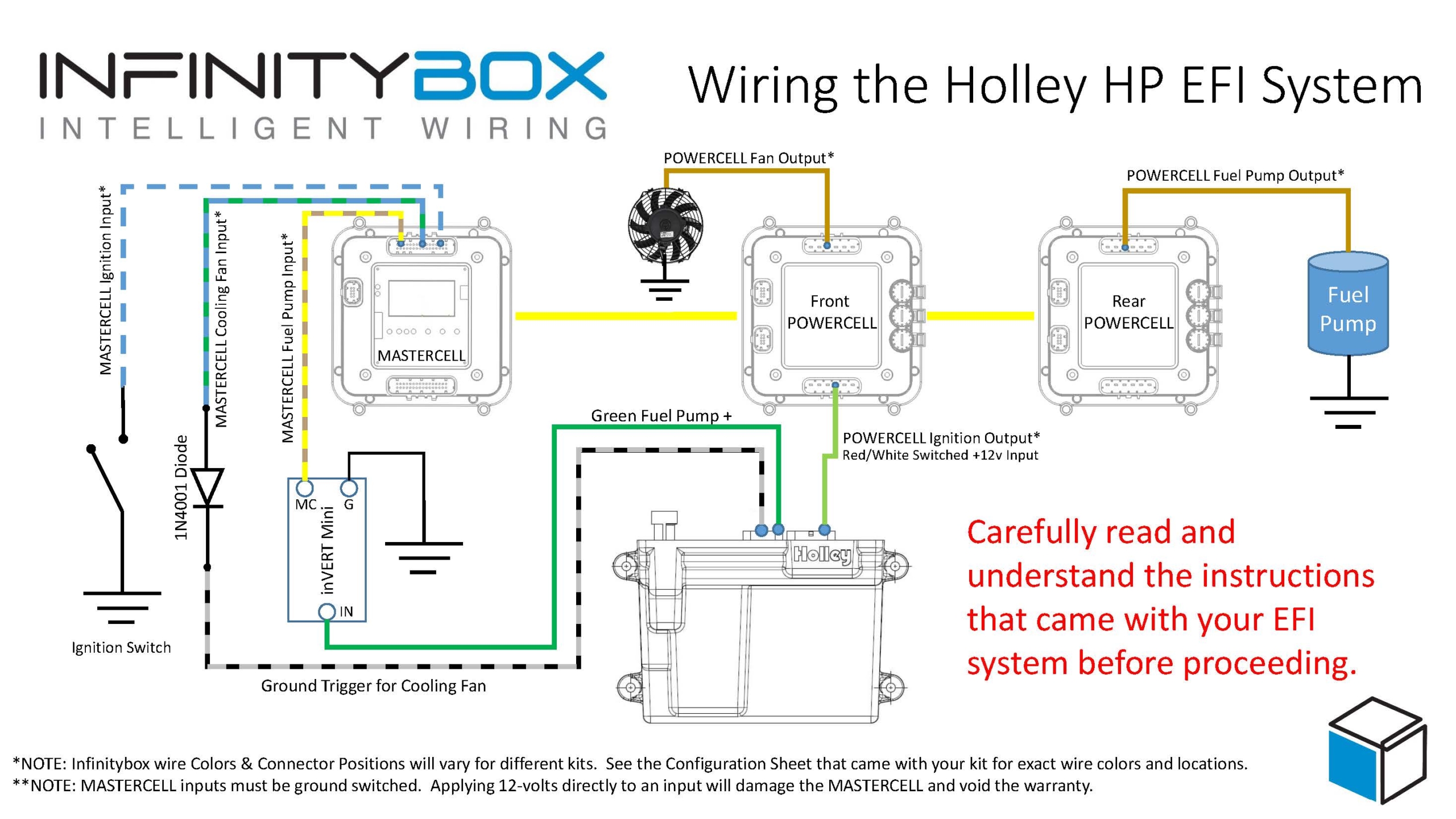
Picture of wiring diagram showing how to wire Holley HP EFI system with the Infinitybox wiring system
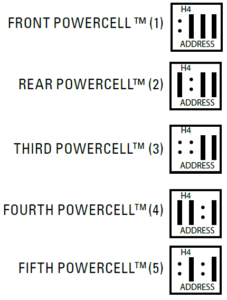
Your Infinitybox 20-Circuit Kit powers the key electrical systems in your car. We’re going to provide the key-on ignition power to the Holley HP system. You are going to connect your POWERCELL ignition output to the 12V Switched wire in the Holley Harness. This is their Red/White wire. In most Infinitybox configurations, your ignition output is the light-green wire on your front POWERCELL but we encourage you to always use your configuration sheet to confirm wire colors in your specific kit. You can get more details on your configuration sheet by clicking this link. When you turn on your ignition switch, the POWERCELL will provide the key-on ignition power that the Holley HP needs to run. You can learn more about wiring your ignition switch to your MASTERCELL by clicking this link.
You can use an output your Infinitybox rear POWERCELL to provide the power to your fuel pump. There are several advantages to using the fuel pump output on your POWERCELL. First, you do not need to use a relay. The POWERCELL has the capability to control 25-amps to your fuel pump directly without a relay. The second advantage is that you can power the fuel pump from the POWERCELL in the back of your car. This keeps your wiring short and easy to install. The Holley HP ECU has a fuel pump trigger that you can connect into the MASTERCELL input for your fuel pump. The Holley fuel pump signal is +12 volts so you must use one of our inVERT Minis to flip this to a ground trigger to go into the MASTERCELL. You can learn more about the inVERT Mini at this link.
You can also use an output on your Infinitybox front POWERCELL to power your cooling fan. You get same benefits with your cooling fan as you do your fuel pump. Your wiring is shorter and you do not need to use an external relay to control the fan. You can either use a thermostatic switch on the engine or you can have the Holley HP ECU send the MASTERCELL the signal to control the fan. This link will show you how wire in a thermostatic switch. The Holley HP ECU has programmable outputs that can be used to signal the MASTERCELL input for the cooling fan. You need to use one of their “G” or ground switched outputs and need to configure this within their software tool. You must use a diode to isolate the output on the Holley HP from the MASTERCELL. See the details in our wiring diagram.
Those are all of the connections that you need to make between your Infinitybox 20-Circuit Kit and the Holley HP EFI system. You can download a PDF of this wiring diagram by clicking this link.
Click on this link to contact our technical support team if you have any questions about wiring your Holley HP EFI system with Infinitybox.
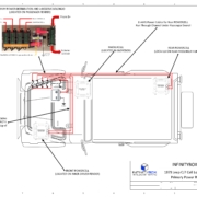
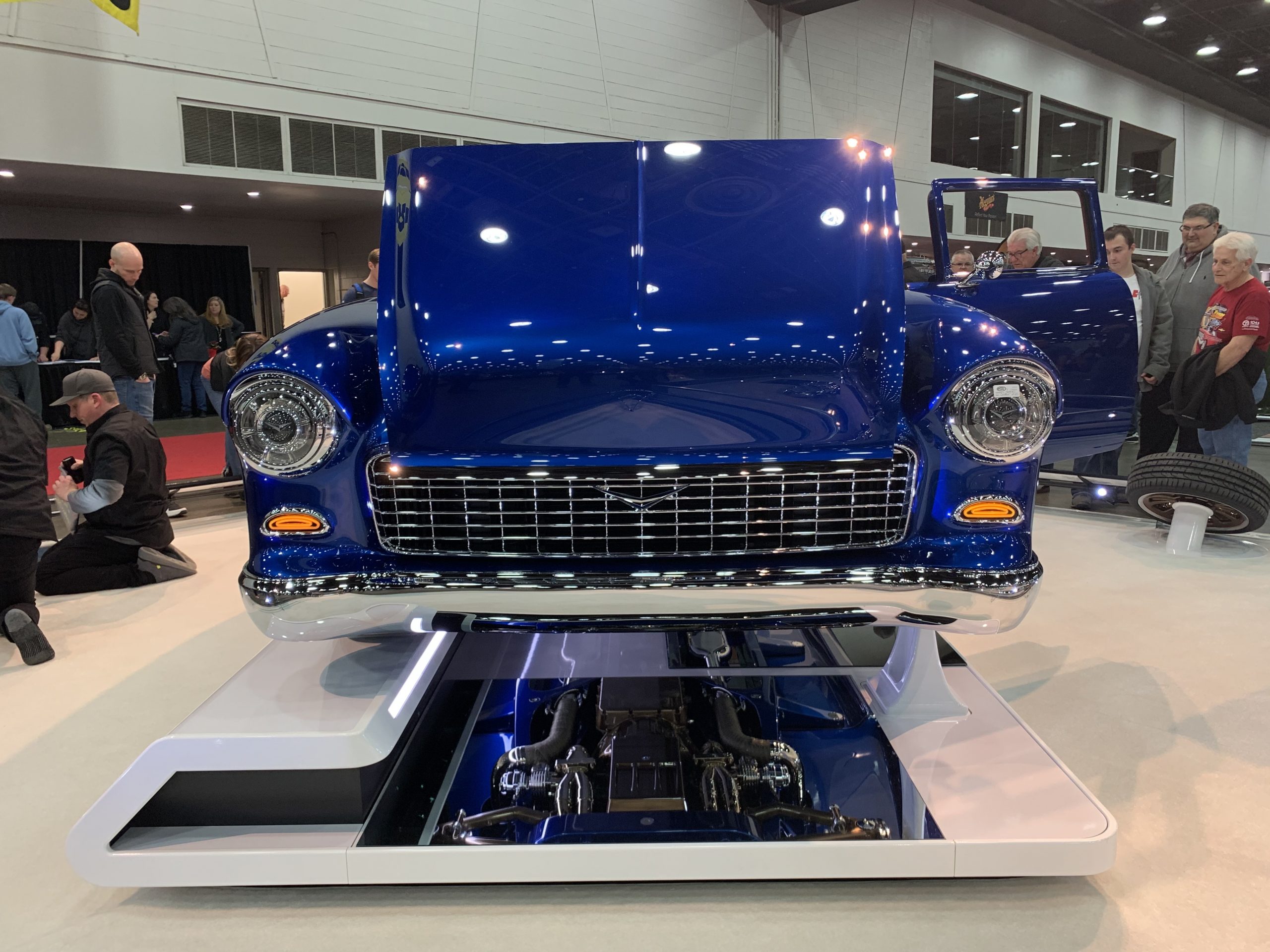
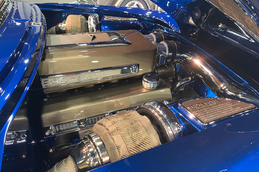
 Image Courtesy of Miranda Built, Inc.


 Copyright Infinitybox 2022. All Rights Reserved.
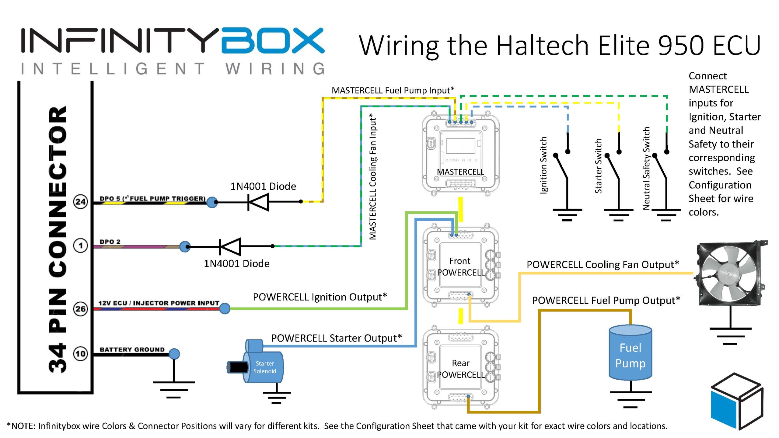
 Copyright Infinitybox, LLC 2021. All Rights Reserved.
  Copyright Infinitybox, LLC 2021. All Rights Reserved.

 Copyright Infinitybox, LLC 2021. All Rights Reserved.
 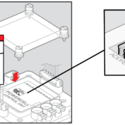 Copyright Infinitybox, LLC 2021. All Rights Reserved.
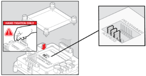


 Copyright Infinitybox, LLC 2021. All Rights Reserved.

