Posts

POWERCELL

Our 20-Circuit Kit is the core to the electrical system in your car.  It is more than just a wiring harness.  It is a universal wiring system that gets you the most advanced, functional and reliable electrical control on the market.  The 20-Circuit Kit starts with our MASTERCELL, which connects to your switches.  It also includes two of our POWERCELLs, which we call the muscles of your system.  The MASTERCELL sends commands to the POWERCELLs to locally power your lights, ignition, starter solenoid, cooling fans, fuel pumps, horn and other accessories.  We’ve talked about the MASTERCELL in more detail in a recent blog post.  You can link to that here.  This post is going to cover more details about our POWERCELL.

The 20-Circuit Kit includes 2 POWERCELLs.  Each POWERCELL can control 10-outputs.  One POWERCELL is for the front of the car, the second is for the rear of the car.  The front POWERCELL is set up to control your headlights, high-beams, turn signals, front running lights, horn, cooling fan, ignition power, starter solenoid and dash power.  The rear POWERCELL is set up to control your rear running lights, turn signals, brake lights, fuel pump, back-up lights, dome lights and other accessories.

Connecting your loads to the POWERCELL is very easy.  You run the output harness from the POWERCELL to your light, fan, pump or other accessory.  You cut our universal harness to length.  You connect our output wire to the wire on your load.  That’s it.  Click on this link to get more details on connecting your POWERCELL outputs to the electrical loads in your car or truck.

You put the POWERCELLs in the car were you need them.  This lets you eliminate size and weight of the wiring harness in your car.  The installation is simpler because the runs of wire are shorter and troubleshooting is easier.

The POWERCELL is a remote fuse and solid-state relay box.  The fuses that you need to properly protect your wiring harness are built into the POWERCELL.  You do not need to add separate fuses.  Also, the solid-state relays that control your loads are built into the POWERCELL.  Each output can carry up to 25-amps continuously so you do not need to add external relays to control your lights, fans, pumps and other accessories.  Also, we don’t use mechanical relays in our POWERCELLs.  Our outputs are controlled by solid-state MOSFETs.  This are rugged and reliable and give you tons of benefits over traditional relays.  Check out this link to learn about some of the advantages of a MOSFET.

This video walks through more of the details of the Infinitybox POWERCELL.

You can easily add extra POWERCELLs to your 20-Circuit Kit if you need to expand the output capacity beyond 20.  Each additional POWERCELL gives you 10 more outputs to your Infinitybox system.  The POWERCELL kit includes the POWERCELL plus all of the harnessing required to connect to your existing 20-Circuit Kit.  You can learn more about the POWERCELL kit by clicking this link.

We have the solid model for the POWERCELL available to our customers to help with their planning and mocking up process.

If you want to purchase our Infinitybox system or have technical questions, you can click on this link to contact our team.

Fuel Pump

Now it is time to wire the fuel pump to the POWERCELL in our 1967 Mustang project.  This is the last major output that needs to be wired in.  In our next series of posts, we will be talking about wiring the switches to the MASTERCELL.

There are lots of different kinds of electric fuel pumps for cars and trucks.  Primarily, they fall into two categories: in-tank and in-line.  These are pretty self-explanatory.  In-tank fuel pumps are mounted in the fuel tank.  In-line fuel pumps are installed somewhere in the fuel line running between the tank and the engine.  Our customer is using an Aeromotive 325 Stealth In-Tank Pump for this project.

Aeromotive Stealth Fuel Pump

Aeromotive Stealth Fuel Pump

Just like everything else in your car, thoroughly read and understand the manual that came with your fuel pump before you start this part of the install.  Remember that you are playing with Gasoline.

Wiring for the fuel pump is pretty simple.  The fuel pump needs battery power and ground.  The battery power is going to come from a POWERCELL output.  The ground connection is going to be made locally to the chassis.

This Aeromotive pump has two wires: red and black.  Black is ground and that is going to connect to the chassis.  Remember how important good ground connections are.  Make sure that you have a reliable metal-to-metal connection between your ground wire and the chassis.

The red wire is power.  This is going to connect to a POWERCELL output.  In most of our configurations, this power comes from output 10 on the rear POWERCELL.  This is the tan wire on the A connector.  The advantage of using our system to power the fuel pump is that the pump gets connected to the local POWERCELL.  The fuse and relay for that pump are built into the POWERCELL.  If you have a POWERCELL mounted in the rear of the car, the power wire going to the pump is very short.

We need to make a few comments about current draw.  Take a good look at the manual or specifications for your fuel pump.  You have 25-amps of steady-state current draw to work with on each POWERCELL output.  Aeromotive publishes great graphs in their manuals that show current draw and fuel flow versus pressure.  At the highest flow rate and highest pressure, this pump draws about 16-amps.  This is well below the 25-amp capacity of a single POWERCELL output.

In some cases, you need to provide power to the fuel level sender in the tank.  If yours needs to be powered, you can splice off the fuel pump output on the POWERCELL.  It is a good time to wire sender power if needed while you’re wiring power to the pump.

That’s it for wiring the fuel pump output.  We’ll talk about wiring the fuel pump trigger to the MASTERCELL in upcoming blog posts.  Click on this link to contact us with questions or comments.

Horn

This is a really easy one.  It’s time to wire the horn on this 1967 Mustang project.  This post is going to talk about how to connect the horn output on the POWERCELL to the terminals on the horn.  It is pretty straight forward.

There is a dedicated output in your 10 or 20-Circuit Wiring Kit for the horn.  In the standard front-engine configuration, it is the orange wire on the front POWERCELL.  This is output 9 on the A connector.  Check the configuration sheet that came with your kit to verify this output.  When the MASTERCELL sees the horn input wire grounded, it sends a command to the front POWERCELL to turn the horn output on.  This applies battery voltage to the horn which makes it sound.  When the horn button is released, the MASTERCELL sees the input wire come off of ground.  The MASTERCELL sends a command to the POWERCELL to turn the horn output off.  Pretty simple.

You are going to run the horn output from your front POWERCELL to the horn mounted in the car.  Most horns have two terminals on them.  One is the switched battery power.  The other is ground.  This picture shows an example horn.  This is the Wolo 315-2T.  The 2T stands for two terminal.

Example of a Wolo Horn

Example of a Wolo Horn

You can see the two terminals in the upper right of the picture.

Most horn terminals are 1/4″ male Quick-Disconnect connectors.  You simply strip the POWERCELL output wire and crimp on a female Quick-Disconnect connector.  Some companies refer to these terminals as Push-On.  Others call them Fast-On terminals.  This picture shows an example of these terminals.

Fast-on female terminal

Fast-on female terminal

You can source these terminals from companies like Del City or Waytek Wire.  Make sure that you are getting the right width of terminal.  You also have to make sure that the terminal is the correct size for the gauge of wire.  Our POWERCELL outputs use 14-AWG wire.  Terminals to mate with 14-16 Gauge wire are usually blue.  Pink or Red terminals are usually for 18-22 Gauge wire.  We recommend using these insulated crimp connectors.  You can use un-insulated terminals but we suggest applying heat-shrink tubing over the terminal to insulate the joint.  You do not want to risk the terminal connected to the POWERCELL output accidentally touching the chassis.

Also, make sure that you are using the correct tool to make this crimp.  As noted in other blog posts, you want to stay away from Radio Shack and Home Depot for car wiring.  This includes for tools.  Also, don’t just use a pair of pliers to crimp these terminals.  A good crimp tool is an important investment and will save you problems down the road.  This link will take you to a good quality crimp tool for these types of connectors.

The other of the two terminals on the horn needs to go to ground.  There is no polarity on a horn so you can connect the POWERCELL output and the ground wire to either of the two terminals.  Use the same Quick-Disconnect connector that you did for the POWERCELL output to connect the ground.  Remember that the size of the ground wire should be the same as the size of the wire feeding the horn.  That is good practice for any electrical connection.  On the other side of the ground wire, crimp on a ring terminal and use a bolt to attach this to the chassis.  Make sure that you have a good, metal-to-metal connection from your ground wire ring terminal to the chassis.  You must remove all dirt, rust, paint, powder coating, oil and grease from the connection.

The example that we used above was for a two-terminal horn.  You connected the POWERCELL output to one of the terminals on the horn.  The other connected to ground.  There are some horns that only have a single terminal on them.  That terminal connects to the POWERCELL output.  The horn grounds to the chassis through its mounting bracket.  The same rules for grounding apply.  You must have a clean metal-to-metal connection between the horn bracket and the chassis.

That’s it for this one.  We’ll talk about wiring the MASTERCELL input wires in upcoming posts.  If you have questions or comments about this post or any of the other steps in wiring this 1967 Mustang, please click on this link to contact our team.

Parking Lights

In our last post, we talked about wiring the headlights and high-beams to the front POWERCELL in your Infinitybox system.  Now it is time for you to wire the parking lights.  What we call parking lights can be called a few different things.  Some guys call them marker lights, some call them running lights or driving lights.  We call them parking lights.  These are the amber lights on the front of your car and the amber or red lights on the rear of your car.  Essentially, you are going to wire them the exact same way that you did for your headlights and high-beams with a few important exceptions.

There are parking lights on the front of your car and on the rear of your car.  Instead of running wire from the front to back of your car to power these lights together, we have dedicated outputs on the front and rear POWERCELLs for these lights.  In the case of our 1967 Mustang project, we power the front parking lights from the POWERCELL in the driver’s fender.  The rear parking lights come from the rear POWERCELL mounted in the trunk.  In both cases, the runs of wire are very short.

Remember that the switch does not connect to the lights.  The switch connects to the MASTERCELL.  We’re going to get into wiring the switches in upcoming blog posts.

In configuration that we are using for this 1967 Mustang, the parking lights are on outputs 6 on the front and 6 on the rear POWERCELL.  These are the yellow wires.  Click here to read the blog post that talks about the configuration sheet.  Run your parking light output wire to the the closest parking light on that side of the car, then splice off of that to go to the second parking light on that side of the car.  The parking light output is going to connect to both the left and right parking light bulbs.  These are wired in parallel.  The other wire in the parking light harness needs to get connected to ground.  Check the documentation that came with your lights for the proper wires for power and ground.  If you are using LED parking lights, the polarity is very important.  LED lights will not work if they are wired backwards.  You can see the headlight blog post to talk about ways to tap between the left and right lights on the car by clicking here.

You are going to use the parking light outputs from the front & rear POWERCELLs to power the lights.  You are also going to tap off of these POWERCELL outputs to power other illumination in the car.  Each POWERCELL output has capacity for 25-amps.  Most parking lights draw about one amp so you have lots of room to spare.

In the front of the car, you are going to tap off of your parking light output to power the gauge illumination and your dash illumination.  That way, you have lights on your gauges and dash when your parking lights are on.  In the rear of the car, you are going to tap off of the parking light output to light your license plate light and any other running lights on the back of the car.

This illustration shows you how the front & rear parking light outputs connect from the two POWERCELLs in the car.

Diagram showing how to power your parking lights from the Infinitybox system.

Diagram showing how to power your parking lights from the Infinitybox system.

We wanted to add a few comments about splicing and tapping off wires in your harness.  We do not recommend products that pierce the wire insulation for making taps.  This is a decent way to make splices in low current applications in sealed enclosures for telecom systems.  We do not recommend these types of taps or splices for the automotive environment.  Vibration, temperature, oil, dirt and grease will cause these taps to fail over time.  We recommend that you use crimp connectors or solder these splices.  If you used either of these methods, the joints should be protected and covered with heat-shrink tubing.

Another great option for creating a sealed junction point is to use our Infinitybox Splice Saver Kit.  This is a simple way to join multiple wires together in a sealed connector.  This pictures shows you an example of how to splice multiple lights to your single parking light output on your front POWERCELL using the Splice Saver Kit.

Wire diagram showing how to wire front parking lights and illumination with the Infinitybox Splice Saver Kit

Wire diagram showing how to wire front parking lights and illumination with the Infinitybox Splice Saver Kit

This picture shows you how you can use the Splice Saver Kit to wire your rear parking lights.

Wiring diagram showing how to wire parking lights and brake lights with an Infinitybox Splice Saver

Wiring diagram showing how to wire parking lights and brake lights with an Infinitybox Splice Saver

Click on this link to contact our team with questions or comments about wiring your parking lights with our Infinitybox system.


Headlights

In our last post, we hit the high-points of wiring the outputs on our Infinitybox POWERCELLs.  Over the next few posts, we are going to go into detail on wiring some of the specific loads in your car.  This post is going to talk about headlights.

Headlights are usually the easiest output to wire and we use them as an example when we’re helping guys wire their cars over the phone.  On the front POWERCELL, there is a dedicated output for the headlights.  Check your configuration sheet for the exact wire color.  This blog post will show you how to do this.  In the case of our 1967 Mustang project, the POWERCELL output wire for the headlights is the white wire.  This is output 5 on the B connector.

From the front POWERCELL, you are going to run the white output wire to your headlights.  It is usually easiest to run the wire to the closest headlight, then splice from there to go to the second headlight.  Essentially, you are wiring the two headlights in parallel.  You can use our Splice Saver Kit to make this connection easy and reliable.

In the previous post about wiring POWERCELL outputs, we talked about ways to connect wires together.  These options include butt-splicing, soldering and connectors.  You can built the splice between the two headlight bulbs in this splice.  This picture shows a simple schematic for wiring the two headlights off of a single POWERCELL output.

Picture of a simple schematic showing how to wire your headlights to the Infinitybox POWERCELL

Picture of a simple schematic showing how to wire your headlights to the Infinitybox POWERCELL

There are going to be two wires on each of your headlights.  One is the 12-volt power coming from the POWERCELL output.  The other is ground, which needs to be connected to the chassis.  If your high-beams are integrated into the same headlight housing, there may be multiple connections.  You need to consult the paperwork or instructions that came with your headlights.

If your headlights are incandescent bulbs, the orientation of the power input and ground wires do not matter.  The current will flow through the filament in the bulb in either direction.  If you headlights are HID or LED, the polarity will matter.  You need to consult the manual for the HID or LED headlight kit.

The standard headlight output on the front POWERCELL is designed for an incandescent bulb.  We can do things with a POWERCELL output that you can’t do with a relay.  Because we are using solid-state relays, we can do something called Pulse-Width Modulation.  That means that we can gradually ramp up the power to an output.

Incandescent bulbs have a high in-rush current.  When the bulbs are cool, the resistance of the filament is relatively low.  When you first turn on the bulb, it will draw a lot of current.  As the bulb and filament heat up, the resistance of the filament increases significantly, which limits the current to its steady-state draw.  This inrush current can be 4 to 10 times the steady state current.  You need to size you wire and the fuse to work with this inrush current.  We have done that for you in our choice of output harness wire.

We soft-start the standard headlight and high-beam outputs on the front POWERCELL.  This essentially smooths out the inrush, which causes less stress on the fuse, the wiring and the light bulb.  You get this feature automatically if you use the standard MASTERCELL input.

You can use this same soft-starting output for LED (Light Emitting Diode) headlight kits.  If you are using HID (High Intensity Discharge) headlights, you need to use a different input to the MASTERCELL.  There is a dedicated input to the MASTERCELL for HID headlights.  If you use this input, the headlight input turns on instantaneously without the soft starting.  We’ll talk more about MASTERCELL inputs in later posts.

While we’re at it, you are going to wire your high-beams exactly the same way as the headlights.  In the case of the configuration that we are using for this 1967 Mustang, the dark-blue wire from the front POWERCELL is for the high-beams.  This is output 7 on the A connector.  You are going to run the high-beam output from the POWERCELL to the first high-beam bulb then splice over to the second high-beam bulb.  Check the documentation that came with your bulbs for proper wiring.  The ground wire on the bulb should connect to the chassis of the car.

Keep watching our blog for more posts on wiring the different outputs on your Infinitybox wiring system.  Click this link to contact our team with questions.

POWERCELL Output

Now it is time to connect the POWERCELL outputs to your loads in the car.  When we talk about loads, we refer to the things that you need to power to make the car work.  These include your headlights, turn signals, ignition systems, starter solenoids, fuel pumps, cooling fans, horns, lights, etc.  All of these loads are going to the connect to each POWERCELL output to get their switched battery power.

This post is going to cover the basics of wiring the POWERCELL outputs.  We will publish several specific posts that will go through the details of how to wire your turn signal outputs, wiring your ignition and starter, wiring cooling fans and other loads.

The automotive electrical system uses a grounded chassis.  This means that each load gets its switched power from some power distribution device.  In your case, it is your POWERCELL.  Current flows from the POWERCELL to the load.  To complete the circuit, the load needs to get connected to ground, which is typically your chassis.  The chassis is connected to the negative post of the battery.  This is how the circuit is completed in your system.

Another thing to remember about your Infinitybox system is that the switches connect to the MASTERCELL.  Your loads connect to the POWERCELLs.  There is no connection between the switch and the load.  That connection comes from a data command sent from the MASTERCELL to the POWERCELLs.  When you turn on a switch, the MASTERCELL tells the POWERCELL to turn on an output.

Your kit includes an A & B output harness for each POWERCELL.  If you have our 10-Circuit Kit with one POWERCELL, you have one each of the A & B harnesses.  If you have our 20-Circuit Kit with two POWERCELLs, you will have two of each.

This picture shows you the POWERCELL A output harness.  It has the wires for outputs 6 through 10.

POWERCELL A Output Harness

POWERCELL A Output Harness

This picture shows you the POWERCELL B output harness.  It has the wires for outputs 1 through 5.

POWERCELL B Output Harness

POWERCELL B Output Harness

Yes, we get that it seems that the A & B designations are reversed for these harnesses.  That designation came from the original layout of the POWERCELLs from our early beginnings.  These designations have stuck and changing over a decade of documentation would be tough.

Please note that the A & B connectors are interchangeable in the POWERCELL output sockets.  A lot of initial problem calls that we get from customers come from the fact that they have these harnesses reversed.  Make sure that you are plugging the correct harness into the correct socket.  The manual that came with your kit shows you the correct orientation.  This picture also shows which connector socket is A & B.

Illustration of Infinitybox POWERCELL labeling output connectors

Illustration of Infinitybox POWERCELL labeling output connectors

Once you get the connectors plugged into the correct sockets, you need to properly ground the POWERCELLs.  Each of of the output harnesses have a black wire.  Both of these black wires need to get grounded to the chassis.  This is to properly ground the electronics in the POWERCELL.  Make sure that you have a good metal-to-metal connection between these ground wires and the chassis.  You must make sure that you remove all dirt, rust, oil, grease, paint and powder coating from this connection.

Next, it is time to start connecting the POWERCELL output wires to the loads in the car.  Remember that your configuration sheet is your road map to do this.  You can review our previous blog post about the configuration sheet as a refresher by clicking this link.  The configuration sheet is going to identify the specific POWERCELL output wire by color for each load in the car.

You are going to run the POWERCELL output to the load.  From there you must connect the POWERCELL output wire to the wiring on your light, fan, horn, fuel pump, etc.  There are many different ways to do this.  People will argue advantages of one method over another.  If done correctly with the right tools, they are all good methods.

One of the easiest ways is to butt splice the POWERCELL output wire to the wire on your load.  For example, you cooling fan will probably have two wires coming from the motor housing.  You can use a butt splice connector to connect the POWERCELL output wire to the wire on the fan motor.  This picture shows an example of a butt-splice.

Picture showing example of splicing wires in our 1967 Mustang Install of the Infinitybox wiring system.

Picture showing example of splicing wires in our 1967 Mustang Install of the Infinitybox wiring system.

The team at Waytek Wire have a great post on their blog called “Splice Connectors 101”.  In this article, they walk you through the basics of splicing wires together.  Click here to read this article. 

What is important is that you use the correct crimp tool and you properly seal the joint.  This seal can be done with heat shrink tubing or you can use butt crimp connectors that already have a heat-shrink jacket over them.  Companies like Waytek and Del City are great sources for the right tools and materials.

Another option is to solder the wires together.  A lot of customers swear by this method or a combination of butt-splicing and soldering.  The advantage is that you get a metallurgical connection between the copper strands of both wires.  Some will argue that this is stronger and more reliable than a pure mechanical crimp of a butt-splice.  Just like the butt-splice mentioned above, this joint must be sealed preferably with heat shrink.  The only warning with soldering is that if too much solder is applied to the joint, it can wick up the strands of the wire flowing away from the joint.  This wicking can make the wire more rigid and susceptible to fatiguing if the joint is stressed mechanically.  Just watch the amount of solder that you are applying to the joint.

The last is to put connectors on both ends of the connection.  This is the most time consuming and costly, but it has advantages down the road if you need to remove the load for maintenance.  There are many different options for connection systems.  Deutsch connectors are very popular in racing.  They are rugged, durable and proven.  Delphi Weatherpack connectors are another option.  They have been proven in the field for decades and are a cost effective option.  You can purchase Weatherpack kits from many different sources that include the proper tools to crimp the terminals.  Here is an example of a Weatherpack kit that includes the tool.

If the POWERCELL output harnesses are not long enough, you can easily extend them using any of the connection methods mentioned above.  You must make sure that you use the right size of wire and the right insulation type.  We use 14-AWG wire for all of the POWERCELL outputs.  This will carry 32-amps continuously, which is very conservative for most aftermarket and racing applications.  We use wire with TXL insulation.  This is a cross-linked wire designed for the automotive environment.  It is oil, dirt, chemical and abrasion resistant.  You can source extra 14-AWG TXL wire at this link.  We can also create custom harness lengths.  Contact our sales team for details.

Just a few last comments about wiring the POWERCELL outputs.  Stay away from Home Depot.  We say this as a joke but it is important.  The same materials that you’d use to wire a house have no place in the car.  That means no wire nuts, extension cords or electrical tape to make connections.  Use only tools and materials that are designed to handle the automotive environment in your car.

Keep watching for the next posts that will detail wiring POWERCELL outputs to some of the specific systems in your car.  If you have any questions, please click on this link to contact our team.

Power Input Cables

Here’s the next step in wiring the 1967 Mustang with our Infinitybox system.  You need to run the power input cables from the Mega fuse holder and connect them to the POWERCELLs.  There are 4 power input cables included in your kit.  They look like this.

POWERCELL Battery Input Harness

POWERCELL Battery Input Harness

These cables have the mating connector that plugs into the circular 8-mm sockets on the POWERCELL.  These cables are 8-AWG and are jacketed in high-durability TXL insulation.  Each POWERCELL gets two of these cables.  This lets you supply a total of 120-Amps to the POWERCELL.

Remember how the POWERCELLs work.  They are mounted locally in the car.  Your functions like lights, fans, pumps, ignition and starter connect to the POWERCELL.  The MASTERCELL sends commands to this POWERCELL through the CAN cable to turn these function on and off.  In addition to the CAN cable that sends commands, the POWERCELL needs to get power from the battery for your switched functions.  These primary input cables supply the power to the POWERCELL.

For this process, make sure that you have disconnected the positive cable from the battery.  Plug the round connector on the end of each of the primary input cable into the POWERCELL and run the cable through the car.  All three of the round connector ports on the POWERCELL are the same.  You can pick any two of these to plug the cables into.

The other end of this cable needs to connect to the terminals on the Mega fuse holders installed earlier in this process.  Cut the cable to length, strip it and crimp on the 8-AWG 5/16″ ring terminals that are included with your 10 or 20-Circuit kit.  Make sure that you are using the right tool to make these crimps.  Poor crimps cause many problems down the road.  This link will take you to a simple tool sold by Del City that can be used for all of your primary power cables and battery cables.

We also strongly recommend covering the exposed area of the ring terminals with heat-shrink tubing.  This will minimize exposed metal areas that can lead to short circuits in the car.  Del City or Waytek are great sources for heat-shrink tubing.

If you need to, you can lengthen the primary power cables.  You can use an 8-AWG crimped butt connector to splice in another length of cable or you can solder the strands together.  Done correctly, either are a acceptable way to lengthen these cables.

This picture shows plugging the primary power cables into the rear POWERCELL in our Mustang project.

Plugging in POWERCELL battery input harness in Infinitybox system installed in 1967 Mustang

Plugging in POWERCELL battery input harness in Infinitybox system installed in 1967 Mustang

This picture shows the two primary power cables plugged into the front POWERCELL.

Front POWERCELL Mounted in 1967 Mustang

Front POWERCELL Mounted in 1967 Mustang

This picture shows the primary power cables connected to the Mega fuse holder block in near the battery in the rear of the car.

Assembled Mega Fuse block in 1967 Mustang wired with our Infinitybox system

Assembled Mega Fuse block in 1967 Mustang wired with our Infinitybox system

Each POWERCELL has three power input ports on it.  You are going to use two of these.  To keep the cell sealed, you must plug the power input dummy plug into the unused port.  This is included in your kit.

Sealing plug for POWERCELL battery input port.

Sealing plug for POWERCELL battery input port.

You can also use one of our POWERPLUGs in the open port.

Power Plug

Power Plug

The POWERPLUG is a very easy way to get fused constant battery power from the POWERCELL.  You can use this to power accessories like engine controllers, transmission controllers, audio and LED tail light controllers.

Now that you have the primary power cables properly connected to the primary fuses and the POWERCELLs, you can move on to the next step.  Stay tuned for the next post.  If you have questions in the meantime, you can contacts us by clicking this link.

Mounting Cells

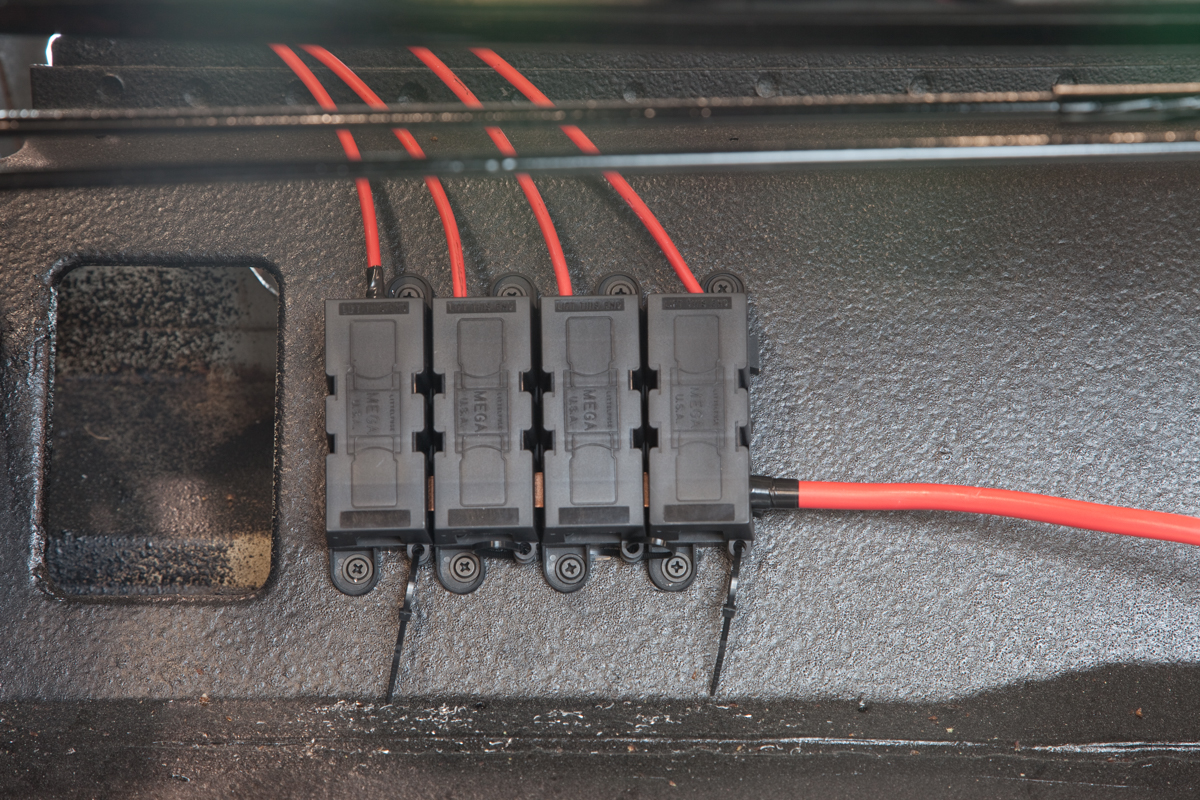
So, here’s where we are in the wiring process for our customer’s 1967 Mustang.  They mounted the primary fuses and ran power from the battery.  Now it is time for mounting cells in the car.  They are using our 20-Circuit Harness kit, which includes one MASTERCELL and two POWERCELLs.  The MASTERCELL connects to the switches in the car (ignition, starter, turn signals, lights, cooling fan sensor, etc.).  The POWERCELLs are where the power comes from to turn on the powered things like the ignition, starter solenoid, turn signals, lights, cooling fan and other accessories.

The Infinitybox system works differently from other wiring harnesses.  With a traditional wiring harness, you have one box with fuses and relays in the center of the car with wire flowing everywhere from this center point.  With the Infinitybox system, you distribute the wiring through the car.  This lets you put the power distribution where you need it to keep the runs of wire short.

The MASTERCELL is going to connect to all of your switches.  Most of these are located around the steering wheel.  That is where you are going to want to mount it.  There are two POWERCELLs in this kit.  One for the front of the car and one for the rear.  You want to mount these POWERCELLs near the things that you are turning on and off.  This keeps the runs of wire short and makes installation easier in the car.

We always suggest that customers start by walking around the car and make a list of the switched electrical functions in the car.  Our configuration sheets are a great planning tool for this.  This link will take you to the standard Front-Engine configuration that is our most popular.  Outside of the normal things like lights, ignition, turn signals, fuel pumps, horns and fans, think about the other things that need switched power like amps, extra lights, transmission controllers and other custom features.

Each cell has 4 mounting points in the corners of the housings.  These are designed for a 1/4″ bolt.  Our preferred mounting method is to use a 1/4″ X 5/8″ shoulder screw.  The advantage with a shoulder screw is that you can’t over tighten the screw and crush the mounting point.  If you are using a traditional bolt, take care not to over-tighten it and crush plastic collar.

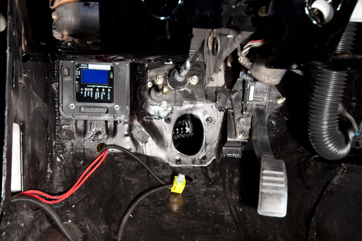
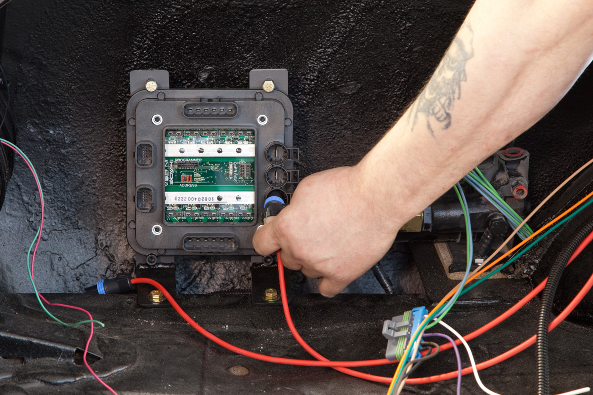
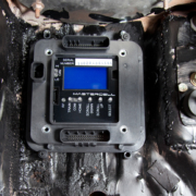
Here are few things to consider when mounting cells.  For the easiest install, you want your MASTERCELL to be as close to the switches as possible.  You can mount your MASTERCELL in the glove box, in the center console, behind, the dash or behind a kick panel.  In the case of this 1967 Mustang, the customer mounted the MASTERCELL above and to the left of the pedal box.  Here’s a good picture.

Infinitybox MASTERCELL mounted next to the pedal box in a 1967 Mustang Resto Mod

Infinitybox MASTERCELL mounted next to the pedal box in a 1967 Mustang Resto Mod

This location is out of the way but still gives them easy access to the MASTERCELL.  The screen on the MASTERCELL is a very important diagnostic tool in the system.  You won’t need to get to this often, but you want to make sure that you can get to it when you need it.  Also if you have our inLINK radio, the antenna is in the MASTERCELL.  You want to make sure that it isn’t buried in the car to get the most range on the key fobs.  There are really no other things to worry about when mounting the MASTERCELL outside of keeping the CAN cables and input wires away from the high-voltage wires on your ignition system.  This is true for any piece of electronics in the car, not just your Infinitybox hardware.

The input wires from the MASTERCELL will connect this cell to all of the switches in the car.  We’ll cover that part in later parts of this install series.

The POWERCELLs are next.  You want to put these close to the things that you are powering.  In the case of the front POWERCELL, this includes your dash power, ignition, starter solenoid, head lights, high-beams, turn signals, running lights, horn and cooling fan.  In the case of the rear POWERCELL, this includes the tail lights, brake lights, fuel pump, reverse lights, turn signals and audio in the trunk.  Remember that your POWERCELLs contain the fuses that protect the wires in your harnesses.  You want to have easy access to these cells in case one of these fuses opens.  There are also diagnostic indicators on the POWERCELLs that give you a wealth of information about how the system is operating.  You want to have good access to the cell to see these indicator lights.

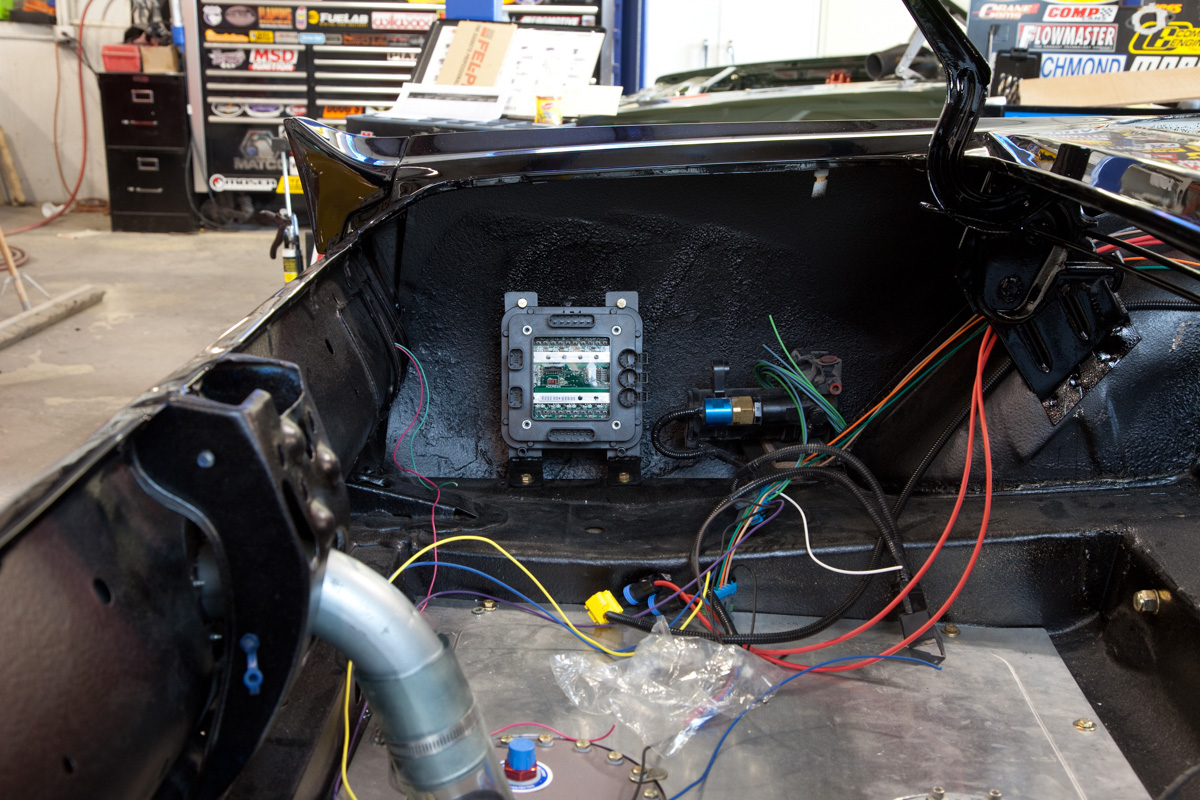
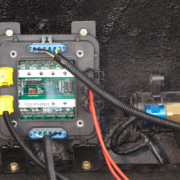
The customer mounted the rear POWERCELL in the driver’s side corner of the trunk.  Here’s a good picture.

Rear POWERCELL in trunk of 1967 Mustang wired with the Infinitybox system.

Rear POWERCELL in trunk of 1967 Mustang wired with the Infinitybox system.

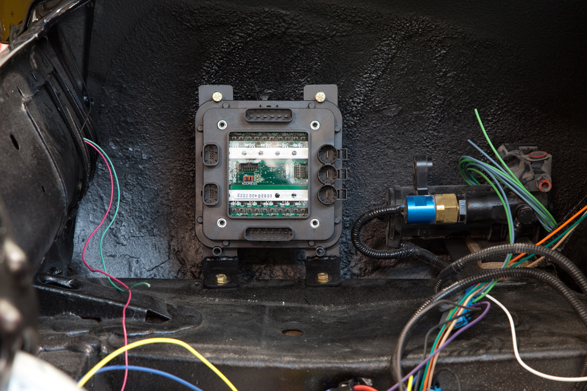
They fabricated a mounting plate to support it nicely.  Here’s a close up shot of the cell and the mounting plate.

Rear POWERCELL mounted in 1967 Mustang wired with the Infinitybox system.

Rear POWERCELL mounted in 1967 Mustang wired with the Infinitybox system.

This POWERCELL will be hidden behind a trim panel in the trunk.  From this location, the runs of output wire to the turn signals, brake lights, fuel pump and running lights is very short and easy to install.

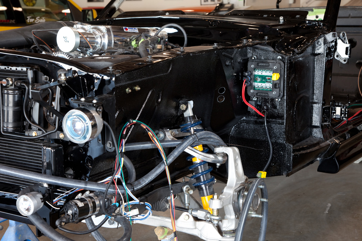
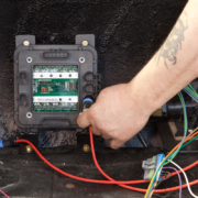
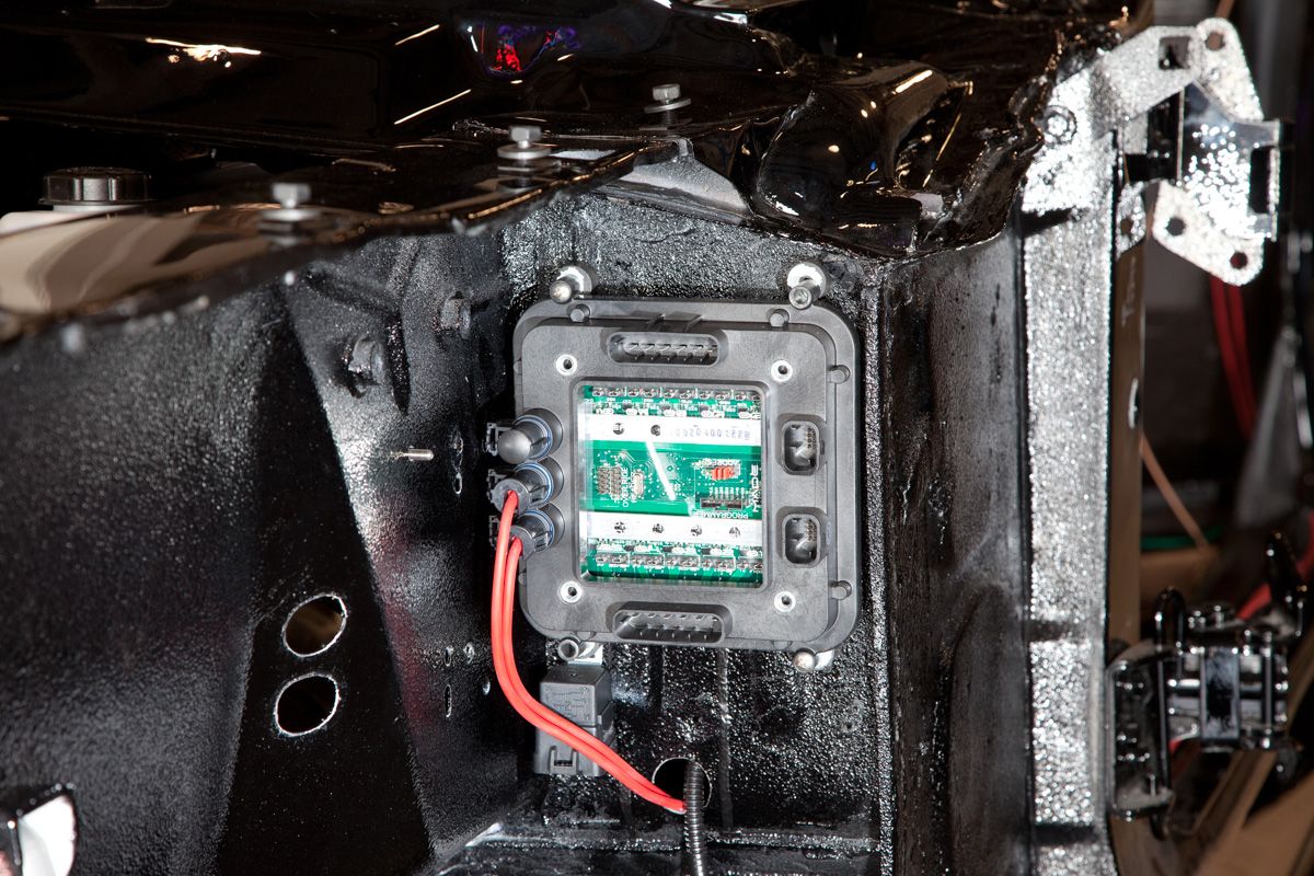
This customer did something unique in their mounting of the front POWERCELL.  They wanted a completely clean engine compartment so they mounted the POWERCELL behind the driver’s fender.  See this picture.

Location of front POWERCELL in 1967 Mustang wired with the Infinitybox system.

Location of front POWERCELL in 1967 Mustang wired with the Infinitybox system.

They fabricated a sealed door inside the wheel well.  They can turn the wheels to the left, open the panel and get easy access to the POWERCELL if they need.  Here’s a closer shot of the mounting location.

Front POWERCELL Mounted in 1967 Mustang

Front POWERCELL Mounted in 1967 Mustang

This location gives them very short runs of wire from the POWERCELL to their ECU, starter solenoid, lights, turn signals, cooling fan, horn and dash power.

Depending on your car and your project, you can mount the POWERCELLs practically anywhere in the car.  The cells are rated to 125 degrees Celsius (260 F).  This means that you can mount them under the hood.  They were designed and tested to survive the temperature, shock and chemical exposure of the under-hood environment.  Like the MASTERCELL and any other piece of electronics in your car, you want to keep them clear of the ignition coils and high-voltage ignition wiring.  You also want to keep them out of the direct radiated heat of your exhaust headers.

Now that mounting cells in the car is complete, the next post will cover running primary power from the Mega fuses to the POWERCELLs.  Stay tuned for this next post.  If you have questions or comments, please click on this link to contact us.