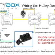
We recently blogged about how you connect the Infinitybox MASTERCELL to the Holley Dominator ECU. The next thing that most guys ask about is how to wire a cooling fan. With the Infinitybox 10 and 20-circuit Harnesses, this is very easy.
Remember that the POWERCELL acts like the fuse and relay box. Built in the cell is the switching device, called a MOSFET, that turns the output on and off. It also includes a fuse to protect the wiring harness against short circuits or other over-current events. You can use the Infinitybox system to control your cooling fan and in most cases, you can eliminate the need for a relay and separate fuses.
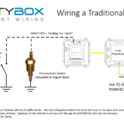
The cooling fan must turn on when the engine temperature reaches a set point. When the engine temperature cools down, the fan should turn off. There are two main ways to do this. Traditionally, you have a thermostatic switch in the radiator or modern ECUs have their own temperature sensors to trigger the fan.
In the first case, you are installing a thermostatic switch into the radiator or the engine block. Most of these switches have a single terminal on them. They have a mechanism built inside that electrically connects that single terminal to its case when it reaches a set temperature. This case is connected to ground by being screwed into the radiator or the engine block. When the temperature drops, the electrical connection between the single terminal and ground is broken.
The MASTERCELL inputs work by being connected to ground. To wire the MASTERCELL input to the thermostatic switch, simply connect the input wire for the cooling fan to the terminal on the switch. See the configuration sheet that came with your kit for the right wire color and connector.
Once you have the input connected to the MASTERCELL, connect the cooling fan output on the POWERCELL to one wire on the cooling fan motor. The other wire needs to connect to the chassis for ground. We recommend using a 25-amp fuse in the POWERCELL output to protect this wire.
This picture shows in detail how you connect the MASTERCELL input to the temperature switch and how to connect the POWERCELL output to the cooling fan motor. You can also download a PDF of the wiring diagram here.
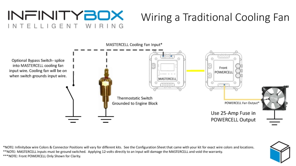
Image of wiring diagram showing how to wire a thermostatic cooling fan switch to the Infinitybox MASTERCELL
Most ECU’s have a trigger that is used to control the cooling fan. They have a sensor that measures engine temperature and they use an external trigger to turn the fan on and off. These cooling fan triggers can either ground switch the cooling fan or they can positive switch the trigger. The manual for the ECU will describe whether the trigger is ground switched or positive switched.
As described above, the MASTERCELL inputs work by being pulled to ground. When the ECU ground switches the cooling fan trigger, it internally grounds the wire when it wants the fan on. In some cases, the voltage on this trigger may float or get pulled to battery voltage when the cooling fan is supposed to be off. This voltage needs to be blocked from flowing back into the MASTERCELL input. To do this, solder a diode in series between the MASTERCELL input and the trigger wire on the ECU. The recommended diode is a 1N4001 and can be easily purchased on-line. When installing the diode, the stripe on the diode should face towards the trigger wire on the ECU. This will not work correctly if the diode is wired in backwards.
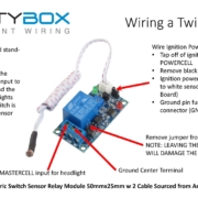
If the cooling fan trigger on the ECU positive switches the cooling fan signal, you need to invert this to a ground trigger for the MASTERCELL. You can do this with a relay. This link will take you to a diagram showing how to do this.
The easier way to convert the positive switch signal from the ECU to a ground switched signal is to use one of our inVERT Mini modules. These are small and fit easily into the harness. This link will take you to more information on the inVERT Mini.
Once you have the MASTERCELL input wired to the trigger on the ECU, you need to wire the POWERCELL output to the fan. This is done exactly the same way as described above for the thermostatic switch example. Connect the cooling fan output on the POWERCELL to one wire on the cooling fan motor. The other wire needs to connect to the chassis for ground. We recommend using a 25-amp fuse in the POWERCELL output to protect this wire.
This picture shows in detail how you connect the MASTERCELL input to the ECU and how to connect the POWERCELL output to the cooling fan motor. You can also download a PDF of this wiring diagram at this link.
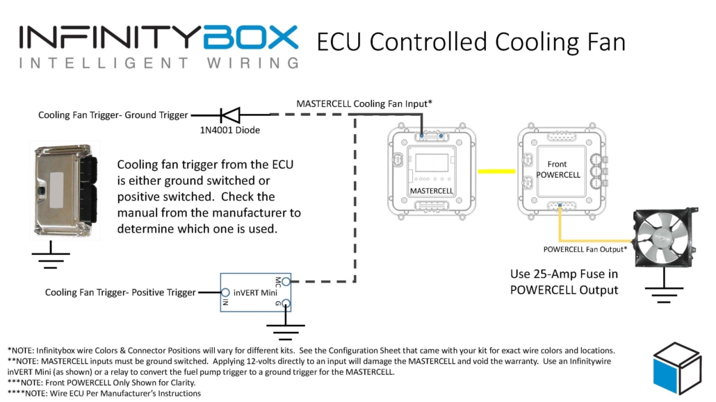
Image of wiring diagram showing how to wire the cooling fan trigger from an ECU to the Infinitybox MASTERCELL
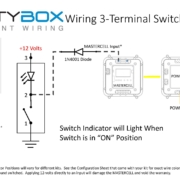
Sometimes, a customer may want to have a bypass switch that they can use to turn on their cooling fans. This is usually a toggle switch on the dash that will turn on the fan at any time, even when the engine is not up to temperature.
In the case where you have a temperature switch, you simply wire the bypass switch in parallel. This means you splice into the MASTERCELL input wire that is going to the temperature switch. You connect the splice to one side of the bypass switch and you ground the other side of the switch. You can see this shown in the wiring diagram for the traditional temperature switch case.
If you’re controlling the fan through the ECU, you do the same thing. You splice into the MASTERCELL input wire for the cooling fan that is going to the ECU. You connect the splice to one side of the bypass switch and you ground the other side of the switch.
Please let us know if you have any questions about how you wire your cooling fans with our Infinitybox 10 and 20-circuit harness kits. You can reach out technical support team at (847) 232-1991 or email us at sales@infinitbox.com. You can also contact our team by clicking this link.

 Copyright Infinitybox, LLC 2021. All Rights Reserved.
 Copyright Infinitybox, LLC 2021. All Rights Reserved.
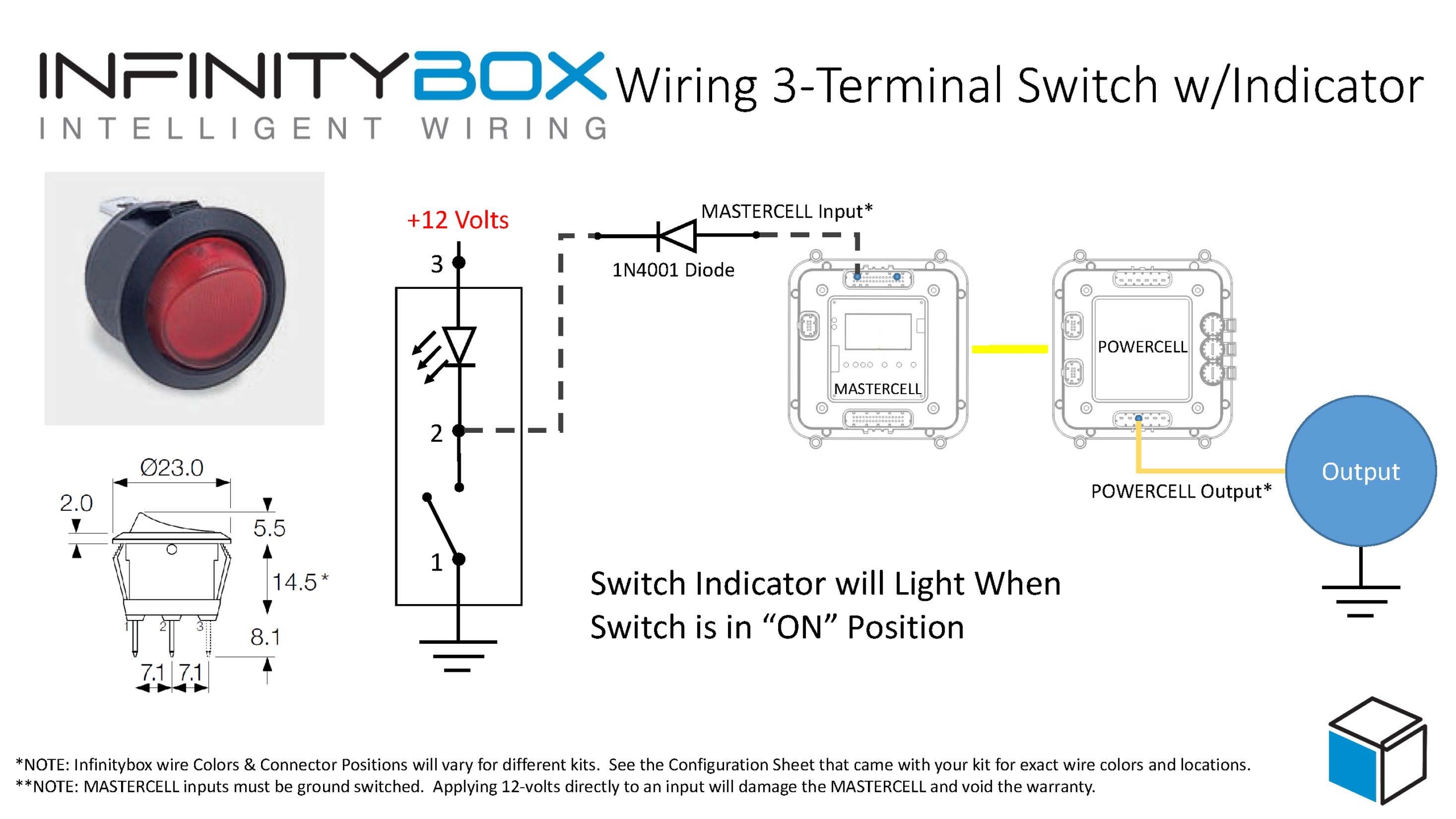
 Copyright Infinitybox, LLC 2021. All Rights Reserved.
 Copyright Infinitybox, LLC 2021. All Rights Reserved.

 Copyright Infinitybox, LLC 2021. All Rights Reserved.
 Copyright Infinitybox, LLC 2021. All Rights Reserved.