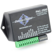
Picture of the Dakota Digital PAC-3500 Module

PAC-3500

The Infinitybox Intelligent wiring system can easily interface with any other electronics modules sold into the restoration and motorsports markets. By pairing our system with other popular accessories, you can enhance the features and functions of your resto mod, Pro-Touring build, street rod or race car. We had a customer call us today asking how he could get a speed sensitive electrical function on his car. This blog post covers that in detail.

This guy built a custom license plate holder for the back of his car. It has an electrically operated linear actuator and he’s using our inMOTION motor controller to raise and lower his license plate. He has one pair of inMOTION outputs wired to the linear actuator. He wants his license plate to be lowered when the car is moving and raise when the car stops. He wants to use this only for car shows and not when he is driving the car on the road.

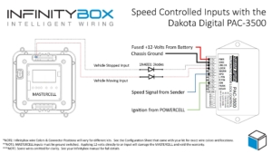
He called us asking how he could get this speed sensitive control with our Infinitybox system. We recommended adding the Dakota Digital PAC-3500 Automatic Door Lock Controller to his system to get this to work. The PAC-3500 takes in the signal from his speedometer sender and uses that to control a lock and unlock input. When the vehicle is moving and the PAC-3500 is getting a speed signal, the module sends out a trigger on one wire. When the vehicle stops moving, the module sends out a signal on a different trigger wire. With the PAC-3500, our customer can easily switch his MASTERCELL inputs to lower his license plate when the car is moving and raise it when the car stops. This diagram shows how to wire the PAC-3500 to the Infinitybox System.

Image of wiring diagram showing how to use the Dakota Digital PAC-3500 with our Infinitybox system

Image of wiring diagram showing how to use the Dakota Digital PAC-3500 with our Infinitybox system

The PAC-3500 needs fused constant power from the battery and a connection to the chassis to ground. It also needs a ignition signal which would come from the ignition output on your POWERCELL. Next, you connect the SPD terminal on the PAC-3500 to the output from your speed sender. Lastly, you connect your MASTERCELL inputs to the LOCK and UNLOCK terminals on the PAC-3500. You must isolate the MASTERCELL from the PAC-3500 using diodes. We recommend a 1N4001 diode. The orientation of these diodes is critical so note their orientation in the wiring diagram.

Whatever MASTERCELL input that you have connected to the LOCK terminal on the PAC-3500 will turn on when the vehicle is moving. Whatever MASTERCELL input that you have connected to the UNLOCK terminal will turn on when the car stops moving. You can set the vehicle speed that turns these on and off by following the instructions in the manual from Dakota Digital. This link will take you to the manual for the PAC-3500.

With the PAC-3500 and our Infinitybox system, you can get speed sensitive control of your electrical system. Raising and lowering this license plate is just one example. You could also use this to lock and unlock your doors with our inMOTION cell. We could set your system to turn off power to your electrical power steering assist above a specific speed. We could use this to raise a wing on the back of the car when you exceed a specific speed. Your options are limitless.

You can download a PDF copy of this wiring diagram by clicking this link.

Give our technical support team a call with specific questions about interfacing the Dakota Digital PAC-3500 to our Infinitybox system to get speed sensitive control of your electronics. You can reach them by clicking this link.

LS3-powered Brunton Stalker Classic wired with the Infinitybox system

Using Open Outputs

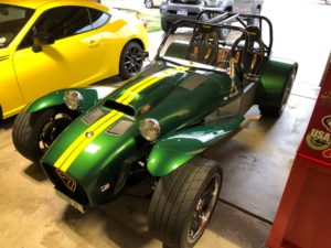
This blog answers a question received from a customer plus shows off the progress on his car.  Mike O just finished his LS3-powered Brunton Stalker Classic.  This is a tribute to the Lotus Super 7.  You can learn more about there car by clicking this link.  His question was about how to use the open outputs on his Infinitybox 20-Circuit Kit.  He wanted to add a water pump and asked if he could use the any of the open outputs to do this.  He also wanted to know how to wire the MASTERCELL inputs to control his open outputs.  We thought that this was a good question that was worth posting up on the blog.

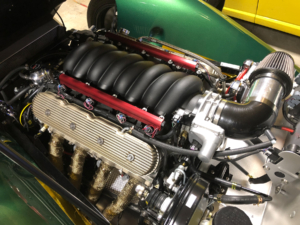
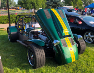
Before we get too technical, let’s talk about the car.  This is another example of a very unique build and shows how simple yet powerful our Infinitybox system can be.  Mike has been working on this car for a while.  He squeezed a 430 hp GM LS3 engine into this chassis all managed by a custom Speartech engine wiring harness.  Considering that the original Super 7’s came with engines the same size as those used in most garden tractors, this LS will make the car fly.

LS3 under the hood of a Brunton Stalker Classic wired with the Infinitybox system

LS3 under the hood of a Brunton Stalker Classic wired with the Infinitybox system

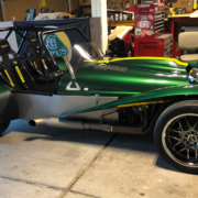
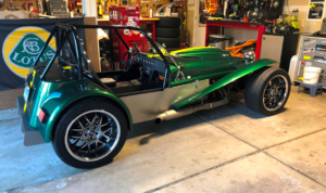
He handcrafted the rear fenders, back panel, cover and rear diffuser out of aluminum.  He custom made the flared wings out of fiberglass.  On top of all of that, he painted it Lotus Racing Green with a yellow racing stripe.  The LS3 is mated to a T-56 6-speed and the brakes are disc from Wilwood.

Brunton Stalker Classic wired with the Infinitybox system

Brunton Stalker Classic wired with the Infinitybox system

Brunton Stalker Classic wired with the Infinitybox system

Brunton Stalker Classic wired with the Infinitybox system

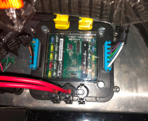
Mike wired the car with our 20-Circuit Kit and inLINK.  The benefit to him was simplifying the wiring, reducing the total amount of wire and giving the flexibility with making changes over his project.  He mounted his MASTERCELL and front POWERCELL just forward of the dash board.  Here is a picture of him laying these out.

MASTERCELL and front POWERCELL installed in Brunton Stalker Classic wired with the Infinitybox system

MASTERCELL and front POWERCELL installed in Brunton Stalker Classic wired with the Infinitybox system

Here is his rear POWERCELL.

POWERCELL mounted in LS3-powered Brunton Stalker Classic

POWERCELL mounted in LS3-powered Brunton Stalker Classic

Okay… now here’s Mike’s question.  He wants to add a Meziere electric water pump to the car.  He originally had a belt-driven water pump.  He wanted to add this electric pump to decrease the load on the engine plus give him more flexibility to cool the car.  Per the manufacturer’s specs, this pump draws 6 to 7-amperes under normal use.  This is well under the 25-amps that a POWERCELL output can supply.

Mike already has the car wired.  With a traditional wiring harness, adding accessories after the fact usually requires running new wires through the car.  With the Infinitybox system, we build in auxiliary outputs that can be used for practically anything.  These outputs can be used for things like extra lighting, multiple fuel pumps, amps, sub woofers and additional cooling fans.  In a typical install, there is 1 open output on the front POWERCELL and 4 on the rear.  Mike simply needs to connect the water pump to the open output on his front POWERCELL.  Then he needs to take the corresponding MASTERCELL input and connect that to a switch for the water pump.  Since he already has the Infinitybox backbone installed in the car, he doesn’t need to run any extra wire through the interior or through the firewall.

The configuration sheet that came with your kit will get you all of the details that you’d need to use these open outputs.  This link will take you to a blog post that gives you more detail on how to read the configuration sheet.  All of the open outputs are set to TRACK.  This means that the output will track the state of the switch.  When the switch is on, the output is on.  When the switch is off, the output is off.  In the case of Mike’s water pump, he can have a switch on the dash what would turn the pump on and off.   He could also wire the MASTERCELL input for his pump directly to the ignition switch so the water pump will turn on when the ignition is on.  You can use this functionality right out of the box with no configuration changes.

We can also custom configure the behavior of these open outputs for you.  One of the most common is to add a timer to the open output used for an electric water pump.  We can set this output to stay on for a period of time after you turn it off.  For example, your electric water pump could continue to run for one minute after the ignition is turned off to help cool down your engine.  Contact our technical support team for more information.

This example shows how flexible and powerful the Infinitybox system can be in your car.  It helped Mike modify the electrical system in his car with minimal changes to add this new water pump.  Thanks to Mike O for asking the question and for sharing the pictures.  The car looks great and we’re proud to be a part of it.

Click on this link to contact our team with any questions about how our Infinitybox system could be used in your project car or truck.

LS3-powered Brunton Stalker Classic wired with the Infinitybox system

LS3-powered Brunton Stalker Classic wired with the Infinitybox system


Example of an automotive 12-volt SPDT Relay

Making Turn Signal Noise

We spend a lot of time educating  customers on what a MOSFET is and why it is better than a mechanical relay.  All of the outputs on our POWERCELLs are controlled by MOSFETs.  They are more efficient than relays, they generate less heat, the have no moving parts, they never wear, we can PWM outputs, etc.  The lists of benefits can go on for hours.  One of the biggest advantages of a MOSFET can also be a disadvantage.  Since it has no moving parts, it makes no noise when it turns on and off.  In the case of turn signals, that can be a disadvantage.

In a traditional wiring system, electro-mechanical flasher modules are used to flash the turn signals.  These are typically bi-metal devices that have been around since the dawn of the automotive industry.  When you turn on your flashers, current flows through a  element in the flasher module.  This heats up a special combination of metals laminated together.  After a short period of time, this element flexes and separates a contact.  When it separates, the current stops flowing and the element cools down.  This lets the element snap back to its starting position which makes the connection again.  The element heats up and the cycle repeats over and over until your turn your signals off.  The mechanical movement of this element in the flasher module is what makes the clicking sound.

This video shows how it works.  Thanks to Chris at Mustang Restorations in Dundee, Illinois for creating this.

You may have noticed in most new cars that the turn signals sound different from most classic cars.  All new cars are using multiplexing technology similar to our Infinitybox system.  This means that they are replacing the traditional flasher module with MOSFET control.  They have tone generators behind the dash that create a synthetic turn signal sound.

Just a quick note about the video above.  If you carefully watch the contacts in the flasher module after Chris removes the cover, you will can see arcing (little sparks) between the contacts as the flasher cycles on and off.  This arcing gradually erodes the contacts in the flasher and causes them to fail over time.  Since our POWERCELL outputs use solid-state MOSFETs, there are no moving contacts to arc and erode over time.  You can flash your turn signals billions of times with no change in their performance.

We occasionally get questions from customers asking how to create a clicking sound when their turn signals are on.  We’ve blogged before about how to wire the turn signal indicator lights on your dash.  This wiring diagram will show you how to get a clicking sound with your turn signals.

Image of wiring diagram showing how to wire the Infinitybox system to get sounds with your turn signals

Image of wiring diagram showing how to wire the Infinitybox system to get sounds with your turn signals

You are going to add a relay behind your dash.  This isn’t going to carry any current, you’re just going to use the mechanical action of the relay to make a clicking sound.  You simply tap off of your POWERCELL outputs for your left and right turn signals.  These get wired to the coil of a relay through two diodes.  These diodes are very important because they isolate the two turn signal outputs from each other.  Without these diodes, both of your turn signals would be connected electrically and would turn on together.  These diodes should be 1N4001.  You can easily get them from Amazon.  The orientation of these diodes is critical.  Please note the position of the cathode in the wiring diagram.  This will not work if they are not oriented correctly.

For all standard relays, the coil terminals are 85 and 86.  Connect your turn signal outputs through the diodes to terminal 86, then ground terminal 85 to the chassis.

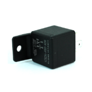
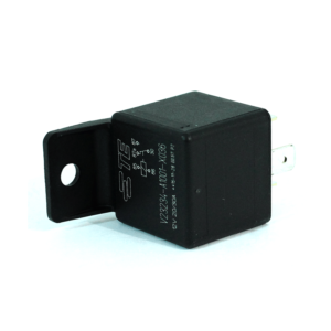
We recommend a relay like this one.

Example of an automotive 12-volt SPDT Relay

Example of an automotive 12-volt SPDT Relay

You can purchase this relay and its terminals at Waytek Wire.  This is a good relay to use because it has an integrated mounting tab.  That makes it easy to mount behind your dash.  It also will help sounds to travel from the relay contacts to resonate your dash.  You want to mount this in a place behind your dash to get good sound transfer.  You may have to experiment with different locations to get the loudest results.

Here’s how this works.  When you flip on your turn signal, the POWERCELL flashes the turn signal outputs.  Power from the outputs flows into the coil of this relay.  This pulls in the relay contact and makes a click.  When the POWERCELL flashes the turn signal off, power is taken away from the relay coil.  The contacts snap back to their rest position and make another click.  This relay isn’t carrying any power, it is just making noise.

You can down a PDF version of this wiring diagram by clicking this link.  
Please let us know if you have any additional questions related to this post or anything else related to our Infinitybox wiring system.  You can contact our technical support team with questions by clicking this link.

Example of a SPDT Switch

Headlights with SPDT Switch

A customer emailed us to ask how he could control his parking lights, headlights and high-beams from a single switch on his dash.  He wanted to use a toggle switch with three positions: down for head lights, up for high-beams and off in the center.  When either the headlights or high-beams were on, he wants his parking lights on.  This is really easy to do with our Infinitybox system.  Check out the details below to see how easy it is to wire your headlights with a SPDT switch.

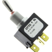
There are many different types of toggle switches.  The major categories are sorted into the number of positions or throws of the switch and the number of poles or contacts.  A single throw switch was two positions.  These are designated as single throw or ST.  A three position switch has two throws from the center position: one up and one down.  These are designated as DT for double throw switches.

The number of poles on a switch designates the number of contacts.  The most common is single pole.  This means that each position on the switch is connected back to a common point with a single terminal.  These are designated as SP switches for single pole.  The more complicated switch is double pole.  These have two terminals for each position or throw of the switch.   This link will take you to a good Wikipedia article that talks about switches in more detail.

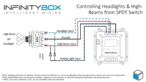
For this application, our customer needs a SPDT switch.  This is a single pole, double throw switch.  The switch has three positions: off in the center and on in the up and down positions.  It has a single pole for each position.  This diagram will show you how to wire MASTERCELL inputs to control the headlights and high-beams off of this Single Pole, Double Throw Switch.

Picture of a wiring diagram showing how to wire a SPDT switch to control headlights, parking lights and high-beams with the Infinitybox system

Picture of a wiring diagram showing how to wire a SPDT switch to control headlights, parking lights and high-beams with the Infinitybox system

The MASTERCELL input for the headlights connects to the top terminal of the switch.  The input for the high-beams connects to the bottom terminal of the switch.  The middle or common terminal of the switch needs to get connected to ground.  This can go to the chassis or can connect to one of the black ground wires in the MASTERCELL input harness.

When the switch is in the middle position, nothing is connected so the headlights and high-beams are off.  When you flip the switch to the down position, the input for the headlights gets connected to the center terminal, which is ground.  This triggers the headlight input on the MASTERCELL.  To turn on the high-beams, you flip the switch to the up position.

For your parking light input, you need to wire this to both the headlight and high-beam contacts on the switch but there is an important step that you need to follow.  If you were to just wire the parking light input to the headlight and high-beam terminals on the switch, all of the inputs would be electrically connected together.  All three outputs would turn on at the same time in either the headlight or high-beam position.  You need to isolate the headlights and high-beams with diodes for this to work properly.  You need to connect the MASTERCELL input for the parking lights to the headlight and high-beam terminals through two diodes.  These diodes should be a 1N4001 rectifier and these can easily be purchased from Amazon.  The diodes act like one-way check valves.  They do not let the parking light input connect between the headlight and high-beam input.  The orientation of these diodes are very important.  If they are wired backwards, this will not work.  Please look at the wiring diagram for proper orientation of these diodes.

When the switch is flipped to the headlight position, the parking light input gets connected to ground through the diode.  The same thing happens when the switch is in the high-beam position.  The parking lights will turn on when the switch is in the headlight of high-beam position if you follow this wiring diagram.

You can download a PDF copy of this wiring diagram by clicking this link.

If you have questions about this wiring diagram or need specific help wiring your car with our Infinitybox system, click on this link to contact our technical support group.

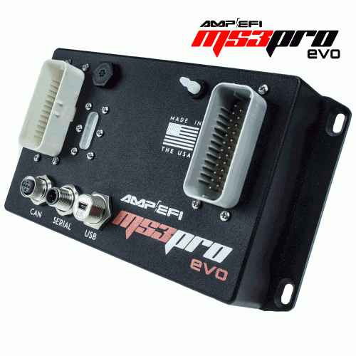
MS3Pro EVO ECU

Here’s another post showing you how to connect your Infinitybox wiring system to a popular EFI system.  We had a customer ask about wiring the MS3Pro EVO ECU with our Infinitybox 20-Circuit Kit.  This is a very powerful engine management system that can be easily connected to Infinitybox.

MS3Pro ECU

MS3Pro ECU

Just like any other ECU, you must thoroughly read and understand the manual that comes with the hardware.  AMP/EFI has a very comprehensive manual that covers all of the details of this ECU.  You can download that by clicking this link.  The other important thing to note about this blog post is that we are only showing how to connect the Infinitybox system to the MS3Pro EVO ECO.  This includes the wiring for ignition power, the cooling fan trigger and the fuel pump trigger.  Consult their manual for the rest of the engine wiring.

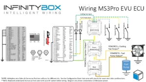
This picture shows the details of wiring the ignition power from your POWERCELL and the MASTERCELL inputs for the cooling fan and fuel pump.

Picture of wiring diagram for MS3Pro EFI system and the Infinitybox system.

Picture of wiring diagram for MS3Pro EFI system and the Infinitybox system.

There are multiple grounds in the MS3Pro EVO ECU harness.  You must have a solid, metal-to-metal connection to ground for all of these wires.

From there, the ECU needs key on power from the ignition.  Consult the configuration sheet that came with your system for the proper POWERCELL output wire for your ignition.  That will connect to terminal 25 on the White Connector on their ECU.  See their documentation for more details.

The ECU is set up to ground switch a relay for the fuel pump.  You can connect your fuel pump input to the MASTERCELL to this pin on their ECU.  You must install a blocking diode to isolate the MASTERCELL from the ECU.  See our wiring diagram for the wire details and for the orientation of the diode.  Improper installation of this diode will make this inoperable.

You can also program the MS3Pro EVO ECU outputs to control the fuel pump.  These outputs are ground switched so they can be wired in a similar way to to the fuel pump.  Just like the fuel pump, you must install a blocking diode between the ECU and the MASTERCELL.  See our wiring diagram for wire details and diode orientation.

For both the cooling fan and the fuel pump, you must not program the ECU to pulse-width modulate these outputs.  They must either be on or off.

You can download a copy of this wiring diagram by clicking on this link. 

Please click this link to contact our technical support team with questions.  

Example of FiTech Go-EFI Fuel Injection System

FiTech Go EFI

The revolution in electronically controlled fuel injection systems has dramatically changed the way that guys build cars.  Not much more than 10 years ago, carbs still reigned supreme.  EFI conversions were hard, required a lot of expertise and didn’t get you all of the performance that you really wanted.  Over the years, we have shown how easily our Infinitybox system can power and interface with the most popular EFI systems on the market.  We recently received an email from a customer asking how to wire the Infinitybox 20-Circuit Kit to the FiTech Go EFI 8 1200 Power Adder Plus.  Just like all the other EFI systems, this is easy.

There are blog posts and wiring diagrams on our website for many different EFI systems.  The FiTech Go EFI wires to the Infinitybox in the same way as other fuel injection systems.

Before you start wiring the FiTech EFI, you must thoroughly read and understand the instructions that came with your kit.  This link will take you to the Go EFI 8 1200 manual.  Note that this blog post is just going to cover wiring ignition power from your Infinitybox system, wiring the fuel pump & cooling fan.  Refer to the FiTech manual for the rest of the wiring details.

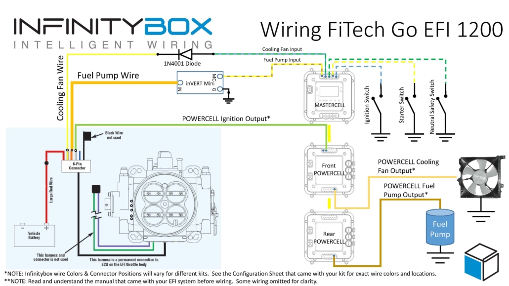
This diagram shows the connections between the FiTech Go EFI harness and the Infinitybox system.

Picture showing how to wire FiTech Go EFI Fuel Injection System with the Infinitybox System.

Picture showing how to wire FiTech Go EFI Fuel Injection System with the Infinitybox System.


First things first, you need to get battery power and ground to the FiTech harness.  The large red wire in their 6-pin connector must go directly to the positive terminal on your battery.

Next, you need to bring ignition power from your POWERCELL to the white wire in their 6-pin harness.  In most Infinitybox systems, the ignition output is the light-green wire on your front POWERCELL but check your configuration to be sure.  This POWERCELL output will supply battery power to the FiTech system whenever you have the ignition switch on.

Next, you need to connect your MASTERCELL input for your cooling fan to the yellow wire on the FiTech 6-pin harness.  You must install a diode in series between the MASTERCELL input and the cooling fan trigger on their harness.  We recommend a 1N4001 diode.  Note that the orientation of this diode is critical.  Check the diagram above for the correct orientation of the stripe on the diode.

There are several advantages to using the Infinitybox system to control the cooling fan directly off of the FiTech harness.  First, you do not need to add a relay.  That is built into the POWERCELL.  Second, our cooling fan outputs are set to soft-start the motor.  Click here to learn more about the benefits of soft-starting.

Next, it is time to wire the fuel pump.  The orange wire on their 6-pin connector is the fuel pump trigger.  This is a 12-volt signal so it cannot be directly connected to the MASTERCELL input for the fuel pump.  You must use an inVERT Mini to flip this 12-volt signal to a ground signal for the MASTERCELL.  This link will get you more details on the inVERT Mini.  The diagram above will show you how to wire the inVERT Mini between the FiTech Go EFI harness and your MASTERCELL fuel pump input.

There are several advantages of using the Infinitybox system to control the fuel pump directly from the FiTech harness.  First, we can disable the fuel pump as a security measure if you have our inLINK Radio upgrade.  More importantly, having the Infinitybox system control the fuel pump means that you  have to run less wire in the car.  The MASTERCELL is located close to the EFI system.  The rear POWERCELL is mounted near the fuel pump in the tank.  There is no extra fuel pump wiring required to make it work.

Wiring your FiTech Go EFI system with Infinitybox is simple and it gets you a powerful electrical system.  You can download a PDF version of this wiring diagram by clicking this link.

Click this link to contact our team with any questions.


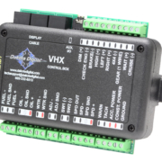
Control module for the Dakota Digital VHX Gauges

Wiring Dakota Digital VHX Gauges

Dakota Digital has been in the business of making advanced electrical products for the Automotive Aftermarket for a long time.  Their products include gauges, lighting, cruise control systems, gear indicators, linear actuators, climate control interfaces and other automotive accessories.  We’ve posted details before on how to wire their cruise control systems and their automatic door lock module.  Their VHX series of gauges has become very popular in the market and a lot of our customers have asked about how to connect their VHX gauge controller box to our Infinitybox system.  This blog post is going to walk you through the details of Wiring Dakota Digital VHX Gauges to our system.

If you are using the RTX gauges, you can click on this link to get to a wiring them.

Before we go too far, this post is only going to cover wiring primary power, ground, key-on power and the signals for the indicators on the dash.  Their manual will cover the details for the rest of the wiring.  Carefully read and understand all of the details of the VHX instructions before you go any further.  You can get their manual by clicking this link.

This diagram shows an overview of the connections to the Infinitybox system for the VHX controller box.

Picture of wiring diagram showing you how to interface your Dakota Digital Gauges with the Infinitybox 20-Circuit Kit

Picture of wiring diagram showing you how to interface your Dakota Digital Gauges with the Infinitybox 20-Circuit Kit

Their VHX controller needs constant power from the battery.  Connect the CONST. POWER terminal on their controller box directly to the positive terminal on the battery.  You must fuse this wire at the battery for safety.  You also have to connect the GROUND terminal on their controller box to a good chassis ground connection.  This must be a metal-to-metal connection that is free of paint, powder coating, dirt and debris.

Here are the connections that are specific to the Infinitybox system.

First, the VHX controller box needs ignition or key-on power.  This is what turns the gauges on when you turn the key in the car.  Your ignition output is going to provide this power.  In most systems, this output is number 3 on the front POWERCELL.  Check the configuration sheet that came with your kit to confirm.  This ignition output is going to power your engine management.  You are going to splice into this wire to connect to the ACC. POWER terminal on the VHX controller box.

Next, you need to connect your parking light output on the front POWERCELL to the DIM(+) terminal on the VHX controller box.  This will turn on the illumination on the VHX gauges when you have your parking or headlights on.  Just like the ignition output, splice into the parking light output on your front POWERCELL and connect this to the DIM(+) terminal.

Lastly, you need to connect the POWERCELL outputs for your turn signals and high-beam to their respective terminals on the VHX control box for the turn signal indicators and high beam indicator.  Just like the key-on power and parking lights, splice into the output wires for the left turn signal, right turn signal and high-beams and connect them to the LEFT(+), RIGHT(+) and HIGH(+) terminals, respectively.  When your POWERCELL is flashing the left turn signal, the indicator for the left turn signal will flash on the Dakota Digital gauges.  When you have your high beams on, your high beam indicator will light up on the gauges.

Our Infinitybox system can power any electrical system in your resto-mod, street rod, pro-touring build or race car.  Wiring Dakota Digital VHX Gauges is a great example of that.  You can download a PDF of this wiring diagram by clicking this link.

Our technical support team is available to answer any questions about blog post or any other topics about wiring your car with our Infinitybox system.  Click on this link to get in touch with our team.


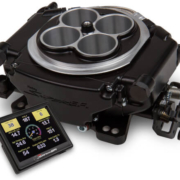
Picture of the Holley Sniper EFI System

Wiring the Holley Sniper EFI

Until recently, electronic fuel injection was completely out of the hands of your typical automotive enthusiast.  Over the past years, many different companies have introduced powerful and elegant systems to bring the benefits of EFI to anyone.  Holley recently introduced their Sniper EFI system.  This is a cost-effective EFI system that can handle up to 650 horsepower and can be tuned without a laptop.  Wiring the Holley Sniper EFI system is a breeze with our Infinitybox 10-Circuit or 20-Circuit Kits.  This blog post will take you through the details.

Our Infinitybox system can interface with any electronic fuel injection system in the market.  Wiring the Holley Sniper EFI is as simple as wiring their Terminator or their Dominator.  Click on this link to get to the details of wiring the Holley Terminator.  Click on this link to get to the details of wiring the Holley Dominator.

Before you start wiring the Holley Sniper EFI, you must thoroughly read and understand the instructions that came with your kit.  This link will take you to the Holley manual.  Note that this blog post is just going to cover wiring ignition power from your Infinitybox system and wiring the fuel pump & cooling fan.  The Holley manual will cover the rest of the wiring details.

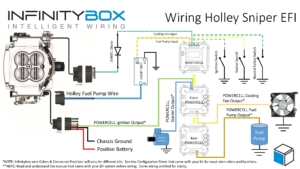
This diagram shows you the connections between your Holley Sniper EFI and your Infinitybox system.

Picture of the Infinitybox wiring diagram showing how to wire the Holley Sniper EFI System with the Infinitybox 20-Circuit Kit

Picture of the Infinitybox wiring diagram showing how to wire the Holley Sniper EFI System with the Infinitybox 20-Circuit Kit

First things first, you need to get battery power and ground to the Sniper.  The red wire in their 7-pin connector must go directly to the positive terminal on your battery.  The black wire in their 7-pin connector must go to ground.  As we discussed in other blog posts, 90% of all electrical problems relate to a bad ground.  Make sure that you have a solid metal-to-metal connection to your chassis with no paint, grease, powder coating or dirt in the way.

Next, you need to bring ignition power from your POWERCELL to the pink wire on their 7-pin harness.  In most Infinitybox systems, this is the light-green wire on your front POWERCELL but check your configuration to be sure.  This POWERCELL output will supply battery power to the Sniper whenever you have the ignition switch on.

Next, you need to connect your MASTERCELL input for your cooling fan to the light-blue wire on the Sniper 10-pin harness.  You must install a diode in series between the MASTERCELL input and the cooling fan trigger on the Holley harness.  We recommend a 1N4001 diode.  Note that the orientation of this diode is critical.  Check the diagram above for the correct orientation of the stripe on the diode.

There are several advantages to using the Infinitybox system to control the cooling fan directly off of the Sniper harness.  First, you do not need to add a relay.  That is built into the POWERCELL.  Second, our cooling fan outputs are set to soft-start the motor.  Click here to learn more about the benefits of soft-starting.

Next, it is time to wire the fuel pump.  The dark-blue wire on the 7-pin connector is the fuel pump trigger.  This is a 12-volt signal so it cannot be directly connected to the MASTERCELL input for the fuel pump.  You must use an inVERT Mini to flip this 12-volt signal to a ground signal for the MASTERCELL.  This link will get you more details on the inVERT Mini.  The diagram above will show you how to wire the inVERT Mini between the Sniper EFI harness and your MASTERCELL input.

There are several advantages of using the Infinitybox system to control the fuel pump directly from the Sniper harness.  First, we can disable the fuel pump as a security measure if you have our inLINK Radio upgrade.  More importantly, having the Infinitybox system control the fuel pump means that you  have to run less wire in the car.  The MASTERCELL is located close to the EFI system.  The rear POWERCELL is mounted near the fuel pump in the tank.  There is no extra fuel pump wiring required to make it work.

One quick note about the Sniper if you are using our One-Button Start feature.  It takes their system 2.5-seconds to boot up.  It is only after that time that the fuel-pump will start to prime.  Our standard One-Button Start feature is set for a 1-second fuel pump prime.  We can easily extend our fuel pump prime time to accommodate the timing required for the Sniper EFI system.  Please talk to Infinitybox technical support when you place your order to make this change.

Wiring the Holley Sniper EFI system with your Infinitybox 20-Circuit Kit will get you all of the functionality that you need to control your engine.  You can download a PDF of our wiring diagram by clicking this link.

Click this link to contact our team with any questions about how our Infinitybox system can streamline your wiring projects.

Passive Keyless Entry Integration

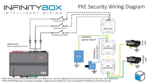
Our customers are very creative.  They are looking for the latest electrical features in their restorations, resto-mods, street-rods, kit cars and Pro-Touring builds.  The Infinitybox system is the only electrical system on the market that can get them the flexibility and the power to fulfill their most creative requirements for their cars and trucks.  We just got this example from Charlie B.  He’s restoring a 1971 Corvette and wanted to integrate a Passive Keyless Entry system into his car.  Check out how he did it with our Infinitybox system.

Charlie is wiring his Corvette with our 20-Circuit Kit.  He wants to integrate as many of the C6 Corvette features as he can into his car.  This includes the Passive Keyless Entry feature and the power door latches found in newer cars.  He purchased a set of the C6 door latches and fabricated them into the B-pillars of the car.  These latches take a 12-volt signal to let you open the door.  He also purchased the C6 door handles that have switches built into them.  When you pull on the handle, it closes a switch that is designed to send a signal to the C6 body computer to trigger the latches.  In this case, our Infinitybox system replaces the body computer from General Motors.

Charlie also purchased the Directed 2102T Passive Keyless Entry System.  He wants to replicate the features of the modern Corvettes in his resto-mod.  When he is away from the car, he wants it to be secured.  The doors can’t open and the car cannot start.  When he approaches the car, he wants to be able to pull on the handles to open the doors and press a button to start the engine.  Our Infinitybox system lets him do all of this.

Even before you get into the Passive Keyless Entry integration, our Infinitybox system has a built-in one-button start feature.  From a single button you can manage your ignition and starter.  You can click on this link to learn more about our One-Button Start.  This makes Charlie’s one-button start requirement easy.  It is standard with every Infinitybox kit.

The 2102T has an output that is called the Starter Kill Output.  It is on the 10-position black connector on the 2102T harness.  The Starter Kill output does exactly what it sounds like.  It is a ground switched output, designed to interrupt the starter relay in the car.  It connects to the ground side of the relay coil.  When the PKE transmitters are out of range of the car, this circuit opens to disable the ability to crank the starter.  When the PKE transmitters are in range of the car, the Starter Kill Output closes and creates a path to ground for the starter relay.  This lets you start the car.

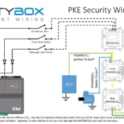
In Charlie’s case, he wants to limit the ability to open the doors of the car and start the car using our one-button start.  For all of these switches, he used the Starter Kill Output on the 2102T to interrupt the ground path for his one-button start switch and the switches for his doors.  The following diagram shows the details.

Image of Infinitybox wiring diagram showing how to limit MASTERCELL inputs using the Directed 2102T Passive Keyless Entry System

Image of Infinitybox wiring diagram showing how to limit MASTERCELL inputs using the Directed 2102T Passive Keyless Entry System

Our MASTERCELL inputs are triggered by a connection to ground.  You connect the input to your switch then ground the other side of your switch.  Turning on the switch closes the circuit to ground, which turns on the MASTERCELL input.  The MASTERCELL then sends a command to the POWERCELLs in the system to control your outputs.  This link will get you more detail on how the MASTERCELL inputs work.  If anything interrupts the electrical path from the MASTERCELL input to ground, the MASTERCELL input will not turn on.  Charlie’s using the Starter Kill Output on the Passive Keyless System to interrupt the ground path to control when his switches will work.

For his one-button start, he connected the MASTERCELL input to one side of his switch then connected the ground side of this switch through a diode to the Starter Kill Output.  He will only get a path to ground for the one-button start switch when his PKE transmitter is in range of the car.  When the transmitter is out of range, pushing the one-button start will do nothing.

For his door latches, Charlie picked two open outputs on his rear POWERCELL.  He wired these outputs to the door latches in the B-pillars and grounded the latches to the chassis.  Then he took the MASTERCELL inputs that corresponded to the POWERCELL outputs and connected them to the switches in the door handles.  Instead of grounding the door switches to the chassis, he connected the ground side of the switch to the Engine Kill Output on the 2102T with a diode in series.  When he pulls on the door handle, the switch in the handle closes.  The MASTERCELL input will get connected to ground when the PKE transmitter is range and the Starter Kill Output is on.  This will cause the MASTERCELL to send a command to the POWERCELL to send 12-volts to the door latch to open the door.

The diodes in this circuit are very important.  They isolate the three inputs from each other so that they can operate independently.  Without these diodes, all three MASTERCELL inputs would turn on if you turned on any one of the switches.  The diodes that we recommend are 1N4001 and can be purchased from any on-line electronics seller.  The orientation of the diodes are very critical.  Diodes are like check valves and they must be oriented in the correct direction.  For this circuit, the cathode must be oriented away from the MASTERCELL input.  The cathode end is the one with the stripe on it.

This simple wiring set up gives Charlie all he wanted for his car security.  If anyone walks up to the car without his PKE transmitters, they can pull on the door handles and nothing will happen.  The doors will not open.  If they were to get inside the car and press the one-button start, nothing would happen.  The car would not start.

If Charlie approaches the car with his PKE transmitters, the 2102T activates and enables the switches for the doors and the one-button start.  He can pull on the door handle and the doors will open.  He can get in the car and press his one-button start.  The engine will start.  All of these features are exactly like what you get in a modern Corvette.

You can download a PDF of this wiring diagram for your project by clicking this link.

Please click this link to contact our technical support team if you have any questions about wiring your car or truck with our Infinitybox system.  

1972 Bronco wired with the Infinitybox system

Creative Key-Less Entry for 1972 Bronco

Our Infinitybox system can do much more than a traditional wire harness.  Even before you get into our accessories, our 20-Circuit Kit is a powerful way to wire your car or truck.  The flexibility that this kit offers lets our customers do some very creating things electrically.  We just got a great write up and set of pictures from Vince C.  He restored a 1972 Bronco and used our 20-Circuit Kit to wire it.

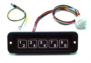
Vince lives by the beach and surfs a lot.  Taking keys with him when he’s out on his board isn’t the easiest thing.  Since it is an open-top truck, he didn’t want to just hide a set of keys in the interior.  He wanted to find a way to eliminate keys completely for his Bronco.  He needed something that could integrate with the inputs on his Infinitybox MASTERCELL.  It had to be easy to install and completely water proof.  He found a company called Essex Electronics.  They make access control systems for doors, gates and vehicles.  They make a key pad that completely fit the bill for Vince.  Their part number is KE-1701 and this link will take you to the data sheet for it.

KE1701 key pad

KE1701 key pad

The KE-1701 is a Piezo-type key pad with up to 7 outputs on it.  You can configure how each of these outputs work including quick on/off, toggling and timers.  All of these are controlled by typing the correct code on the key pad.

Vince wired the outputs of this key pad into inputs on his Infinitybox MASTERCELL.  He can enter a specific code on the key pad to disable security on the truck.  This lets him use our integrated one-button start to control the engine.  He can also enable security from the key pad.  We programmed the system so that a POWERCELL output flashes a light on his dash to indicate to a would-be thief that the truck is protected.

He also has an output wired from the key pad to a different MASTERCELL input that drives a POWERCELL output to pop a solenoid to open his glove compartment.  That way he has a secure place for his wallet and phone when he’s out surfing.  These are well protected and he doesn’t need keys to access them, just the code for the key pad.

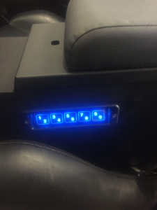
This picture shows how me mounted the key pad on the side of the center console in the Bronco.

Keyless touch panel mounted in 1972 Bronco

Keyless touch panel mounted in 1972 Bronco

This picture shows the wiring diagram for the KE-1701.  You can download a PDF of this diagram at this link.

KE1701 wiring diagram

KE1701 wiring diagram

Vince used the violet wire from the KE-1701 to operate security on his Infinitybox system.  To enable or disable security, he enters his code then presses the 3/4 button within two seconds.   He used the pink wire from the KE-1701 to activate the MASTERCELL input for the glove box solenoid.  To open this, he enters his code then presses the 7/8 key within two seconds.  The operation is very simple and requires no keys.

This is a great example of the power of the 20-Circuit Kit.  Our Infinitybox system makes this integration very easy for him.  He doesn’t need to add any external relays since the high-current switching is built into our POWERCELLs.  Since we’re managing the fuel pump, ignition and starter solenoid, our integrated security features completely immobilize the car.  Lastly, our integrated one-button start feature eliminates the need to wire in a separate controller.

If you have any questions about how you can get creative electrical functionality in your car or truck, click here to contact our technical support team.  Click on the same link if you have an Infinitybox project that you want to show off on our blog.