Holley Terminator EFI
Our Infinitybox system can power any ignition and fuel injection system out there. We recently received a request for a wiring diagram for the Holley Terminator EFI system. We’ve blogged before about the Dominator and given detailed instructions on how to wire that system with our 20-Circuit Kit. You can see that here. This post will cover how to connect to the Holley Terminator EFI system with our 20-Circuit Kit.

Holley ECU
Holley Terminator EFI System
This link will take you to more information on the Holley Terminator EFI system.
Our Infinitybox 20-Circuit Kit is going to provide the ignition power to the Holley ECU. It is also going to take the fuel pump trigger signal from their ECU and the cooling fan trigger. These two triggers will go to the MASTERCELL which will send signals to the POWERCELL in the front of the car for the cooling fan and the POWERCELL in rear of the car for the fuel pump. This eliminates the need to add external relays because they are switched from inside the POWERCELLs. This also eliminates the need to run high-current wiring from the Holley Terminator EFI system to the front and back of the car. Those signals are sent through our CAN cable.
Before we go any farther, it is very important that you completely read and fully understand the manual that came with your Holley Terminator EFI system. There are many different parts of properly installing this system, the wiring is just one step.
Once you have read and understand their manual, you must make all of the constant power and ground connections necessary for their system to work. There are multiple constant power feeds that must be wired directly to the battery and multiple ground connections. You must also wire in all of the other connections including the coil, tach, O2 sensors, etc. Their manual will cover these details.
As an overview, here are the points where your 20-Circuit Kit will connect to the Holley Terminator EFI system.
- The ignition output on your POWERCELL will supply the key-on power to their system.
- Their system will trigger the fuel pump output on your rear POWERCELL from the MASTERCELL.
- Their system will trigger the cooling fan output on your front POWERCELL from the MASTERCELL.
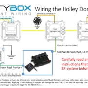
This picture shows you the overview of the connections between your Infinitybox 20-Circuit Kit and the Holley Terminator EFI system.
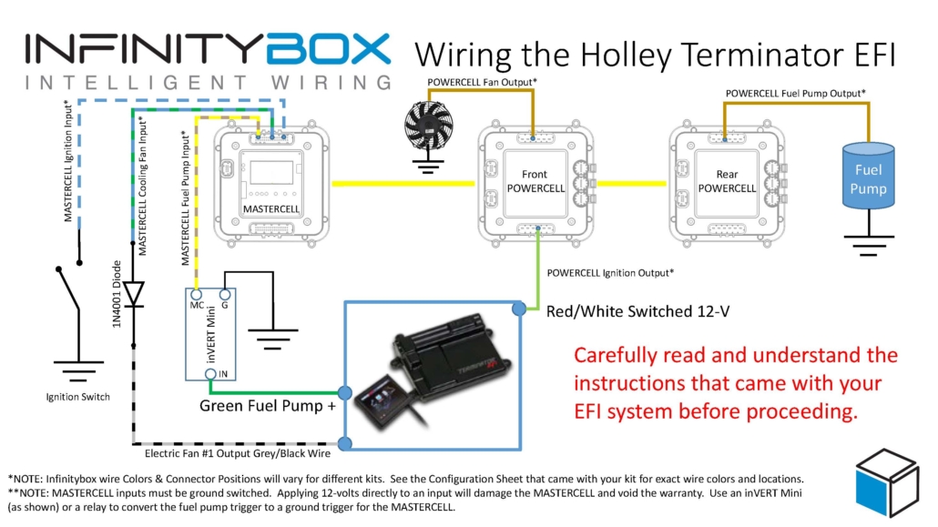
Picture of Infinitybox wiring diagram showing how to wire the Holley Terminator with the 20-Circuit Kit.
You can download a PDF of this wiring diagram by clicking this link.
Let’s start with the key-on ignition power. Check your configuration sheet and find the ignition output wire. In most cases, this is the light-green wire on the front POWERCELL. System configurations may vary so check the configuration sheet that came with your kit. The POWERCELL ignition output wire is going to connect to the red wire with the white stripe in the Holley ECU harness.
Next, you need to connect the fuel pump trigger. In the ECU harness, there is a green fuel pump wire. This wire supplies 12-volts to drive a pump directly or to drive a relay coil. To connect this to the MASTERCELL input, you must convert this 12-volt signal to a ground signal. You can do this with one of our inVERT Mini’s. Alternately, you can use a relay to flip this 12-volt signal to a ground signal for the MASTERCELL. This link will take you to a diagram showing you how to use a relay if you don’t want to use an inVERT Mini.
Check the configuration sheet that came with your kit. Find the MASTERCELL input wire for your fuel-pump. In most cases this is input 19 which is the tan wire with the yellow stripe. Check your configuration sheet to confirm this as different systems may have different wire colors.
Lastly, you need to wire the cooling fan trigger from the Holley Terminator EFI system to your MASTERCELL. Check your configuration sheet for the color of this wire. In most systems it is the blue wire with the yellow tracer.
There are additional outputs on the Holley harness. The gray wire with the black stripe is the cooling fan trigger. This is a ground-switched signal so you do not need to flip it to connect it to the MASTERCELL. However, we do recommend using a diode to eliminate the chance of surges coming into the MASTERCELL inputs from the ECU. A 1N4001 diode will do the job. You can get these from any electronics source. Please note that the orientation of the diode is very important. The stripe on the diode should be on the ECU side of the connection, facing away from the MASTERCELL.
That’s it. When you turn the key, the front POWERCELL is going to apply battery power to the ignition input on the Holley Terminator EFI system. When the Terminator wants the fuel pump to turn on, it will send a signal to the MASTERCELL, which will control the fuel pump through the rear POWERCELL. When the Terminator wants to turn the cooling fan on, it will send a signal to the MASTERCELL. The MASTERCELL will tell the front POWERCELL to turn on the cooling fan.
If you have questions about wiring diagram or wiring anything else with our Infinitybox system, click on this link to contact a member of our team.

 Copyright Infinitybox, LLC 2021. All Rights Reserved.
 Copyright Infinitybox, LLC 2021. All Rights Reserved.
  Copyright Infinitybox, LLC 2021. All Rights Reserved.
  Copyright Infinitybox, LLC 2021. All Rights Reserved.
  Copyright Infinitybox, LLC 2021. All Rights Reserved.
 Copyright Infinitybox, LLC 2021. All Rights Reserved.
  Copyright Infinitybox, LLC 2021. All Rights Reserved.
Trackbacks & Pingbacks
[…] Wiring the Holley Sniper EFI is as simple as wiring their Terminator or their Dominator. Click on this link to get to the details of wiring the Holley Terminator. Click on this link to get to the details of wiring the Holley […]
Leave a Reply
Want to join the discussion?Feel free to contribute!