GTR Start Stop Button
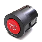
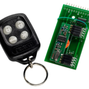
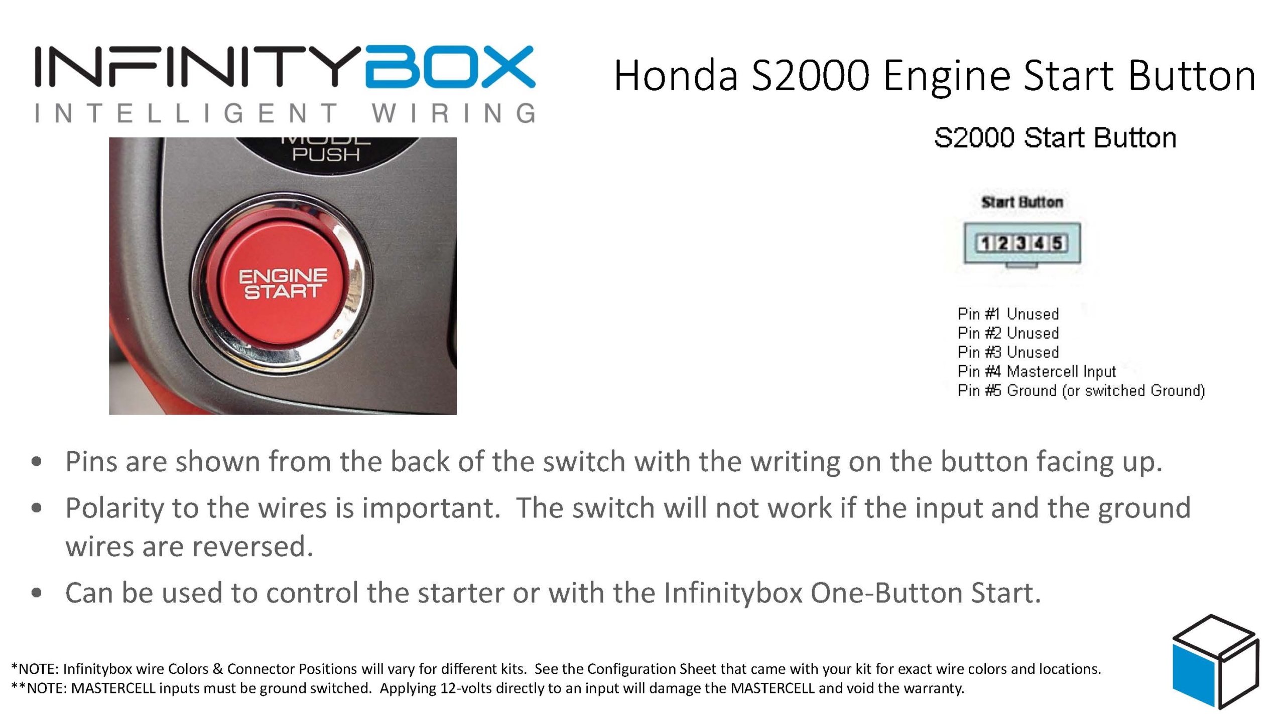
In previous posts, we showed how to take the Engine Start button from a Honda S2000 and use it with the One-Button Start feature built into the Infinitybox system. A single push of this button turns on your ignition and cranks the starter. Just like a lot of modern cars, you can get this feature in your hot-rod, resto-mod or kit car. The Honda S2000 button is pretty popular with our customers. So is the Nissan GTR Start Stop Button. It is very well built, has a great feel to it, mounts easily in practically any dash and works well with our Infinitybox system. The GTR Start Stop Button has the added feature of some extra lights built into the switch that can indicate when the engine is running.
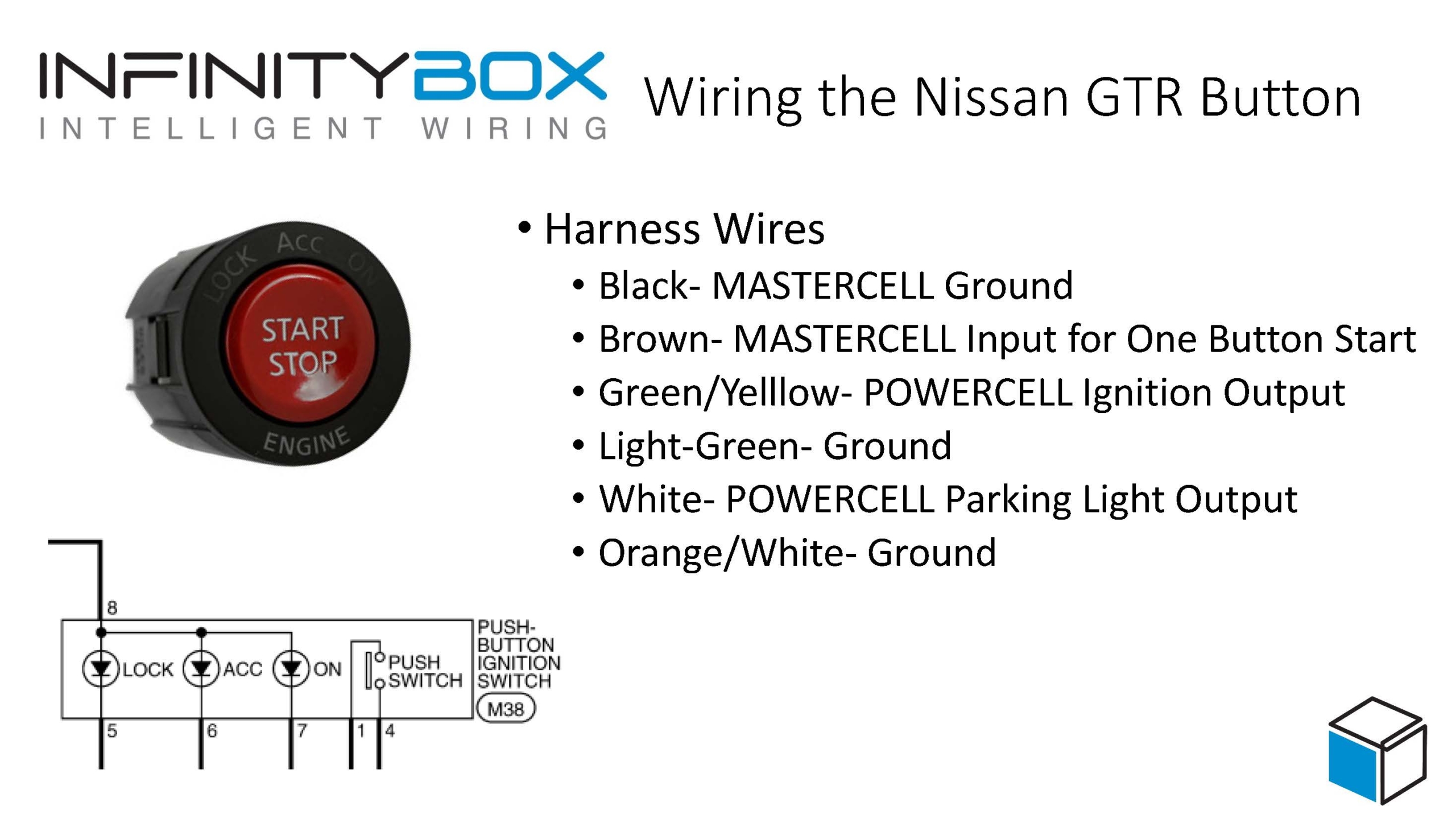
You can purchase the GTR Start Stop Button from many different on-line retailers. When you buy it, you want to make sure that you get the pig-tail harness that plugs into the back of the switch. Having this harness will make your life easier. Different harnesses may have different wire colors in them so you want to pay attention to the numbers of the pins in the connector on the back of the switch. These numbers are molded into the plastic. You may need a magnifying glass to see them. There are 8 pins on the back of the switch. We’re only going to use a few of them.
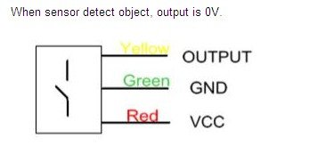
Remember how the MASTERCELL inputs work. You simply connect the input to ground through your switch. When the MASTERCELL sees this ground signal, it starts the process of turning a POWERCELL output on. Since there is very little current required to turn on a MASTERCELL input, you can safely use a switch like the GTR Start Stop Button to control outputs with no extra relays.
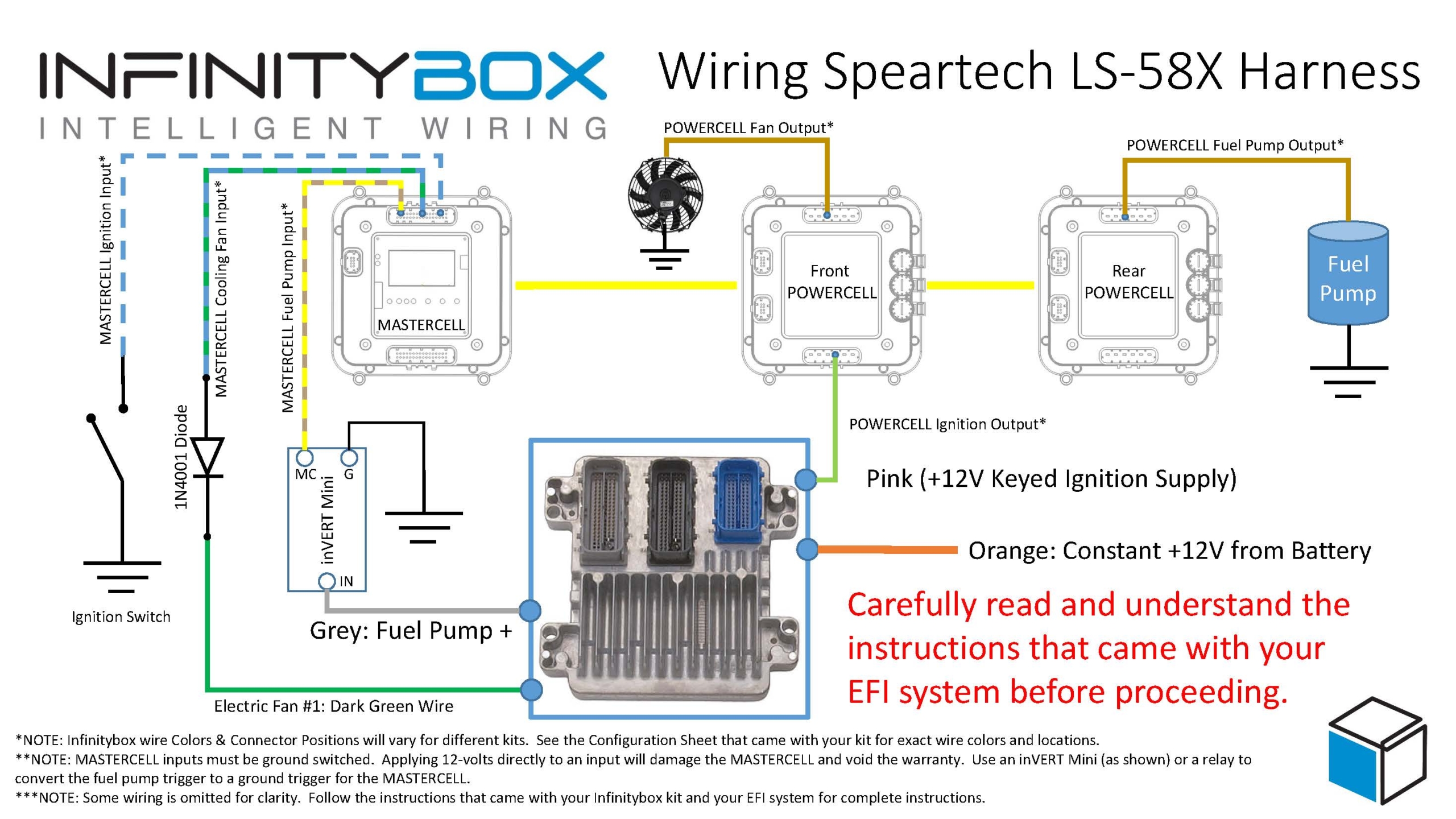
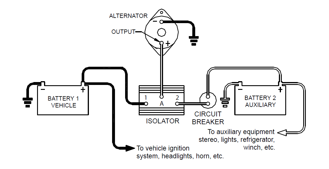
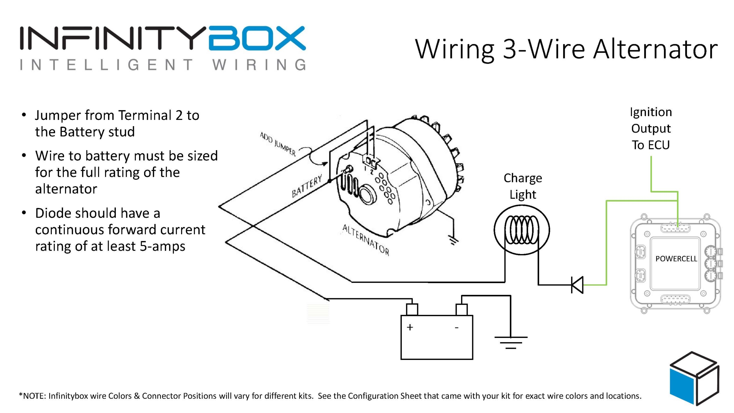
This diagram shows a simplified schematic for the GTR button and which wires connect to the pins on the back of the connector.
Picture of wiring diagram showing how to connect the Nissan GTR Start Stop button to the Infinitybox system to manage the One-Button Start
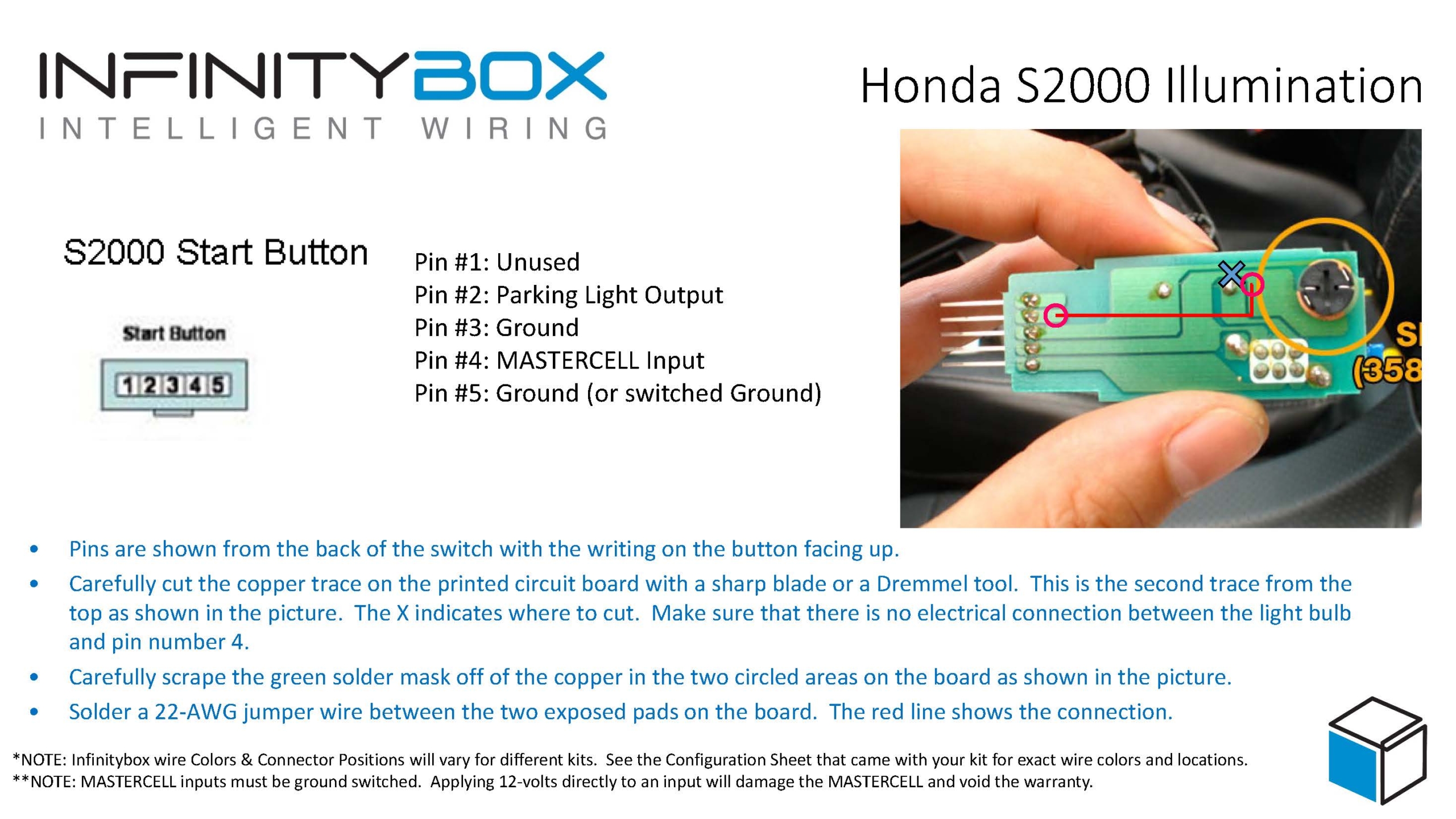
You can also tap into the Ignition output on your POWERCELL and bring that to pin 8 on the switch. You then need to ground pin 7. When you wire it like this, the ON light built into the switch will light up to indicate that your ignition is on.
When you wire the GTR Start Stop button to the Infinitybox one-button start input, you simply press and hold the button to start the car. When you press it, the POWERCELL turns on the ignition output then waits for one second. After that, the POWERCELL turns on the starter output to crank the engine. After the engine starts, you release the button. Your engine is running. To shut down the engine, you simply press and release the button again. Just like most new cars.
You can download a PDF version of this wiring diagram by clicking this link.
Please let us know if you have questions or comments about wiring any car or truck with our Infinitybox system.
 Copyright Infinitybox, LLC 2021. All Rights Reserved.


 Copyright Infinitybox, LLC 2021. All Rights Reserved.
 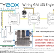 Copyright Infinitybox, LLC 2021. All Rights Reserved.