 Copyright Infinitybox, LLC 2021. All Rights Reserved.
 Wiring the AEM Infinity ECU

AEM Infinity ECU
As we’ve blogged about before, our Infinitybox system easily integrates into any fuel injection or engine management system. With our Infinitybox system and your ECU, you can easily power your engine management system plus seamlessly control your fuel pump and cooling fans. We have a lot of different examples of wiring diagrams for different ECU’s. You can get to them in the Resources section of our website by clicking this link. This post is going to cover connecting your AEM Infinity ECU to your Infinitybox 20-Circuit Kit.
AEM has created a very powerful series of engine management computers and electronic fuel injection systems. You can learn more about their product offering by clicking this link. Before you start to wire their ECU, you must carefully read and thoroughly understand the instructions that came with your AEM Infinity ECU. They have a very comprehensive set of instructions that walk you through the entire process. Check their website for the specific manual for your ECU.
This blog post and wiring diagram are only going to cover the connections between your ECU and the Infinitybox system. Specifically, this includes the ignition output that will supply key-on power to the ECU. It will also include the details on the fuel pump and the cooling fan. See the AEM manual for the rest of the wiring details.
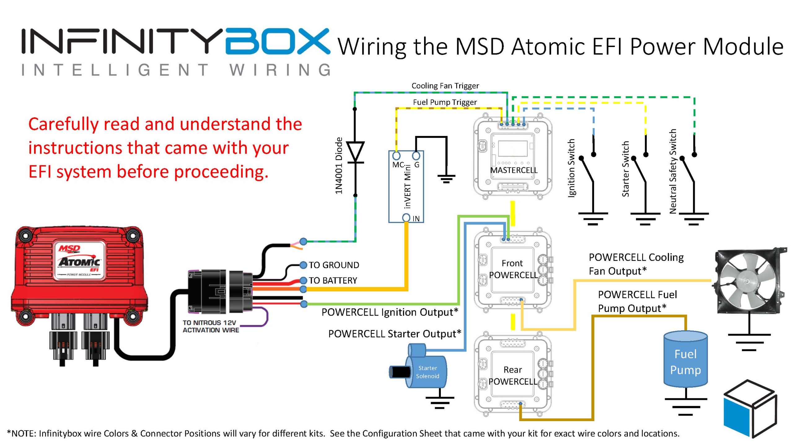
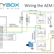
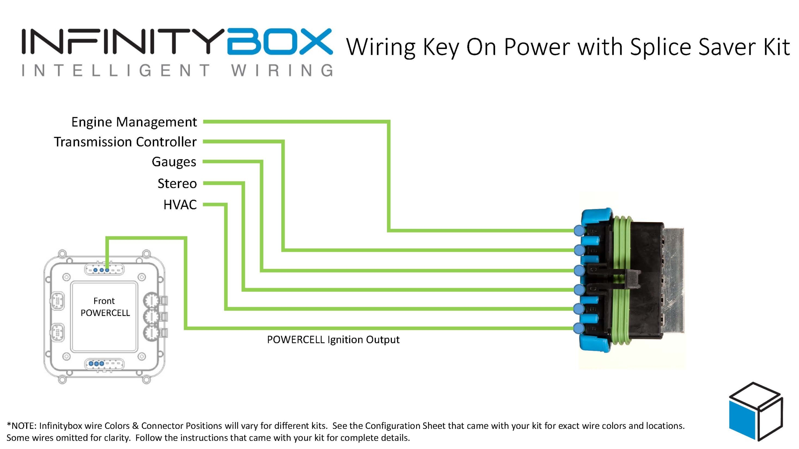
The following diagram shows you all of the connections between the AEM ECU and the Infinitybox 20-Circuit Kit.
Picture of wiring diagram showing how to wire the AEM Infinity ECU with the Infinitybox 20-Circuit Kit
Please note that the wire colors and connector positions shown in this diagram are representation of a typical installation. Reference the specific configuration sheet that came with your Infinitybox kit for the exact wire colors and connector positions.
The first connection that needs to be made is from the front POWERCELL to the Ignition Switched Power on the AEM ECU. This is going to cavity 48 on the C1 connector on their harness. When you turn on your ignition, you will get battery voltage on this pin of their connector.
The next connection is for the fuel pump trigger. Connect the MASTERCELL input for your fuel pump to the PUMP terminal on cavity 41 on the C1 connector. Note that you must add a blocking diode in series on this MASTERCELL input. This can be a 1N4001 diode. The orientation of this diode is critical for correct operation of the fuel pump. Check the wiring diagram for the proper orientation of this diode.
Once you have the MASTERCELL input wired for the fuel pump trigger, connect the fuel pump output from the rear POWERCELL to your pump.
When the ECU sends the signal to turn on the fuel pump, the MASTERCELL input will get the trigger. The MASTERCELL will send a command to the rear POWERCELL to turn on the fuel pump. This lets you eliminate the fuel pump relay in the AEM harness and eliminates the need to run a separate fuel pump wire to the back of the car.
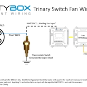
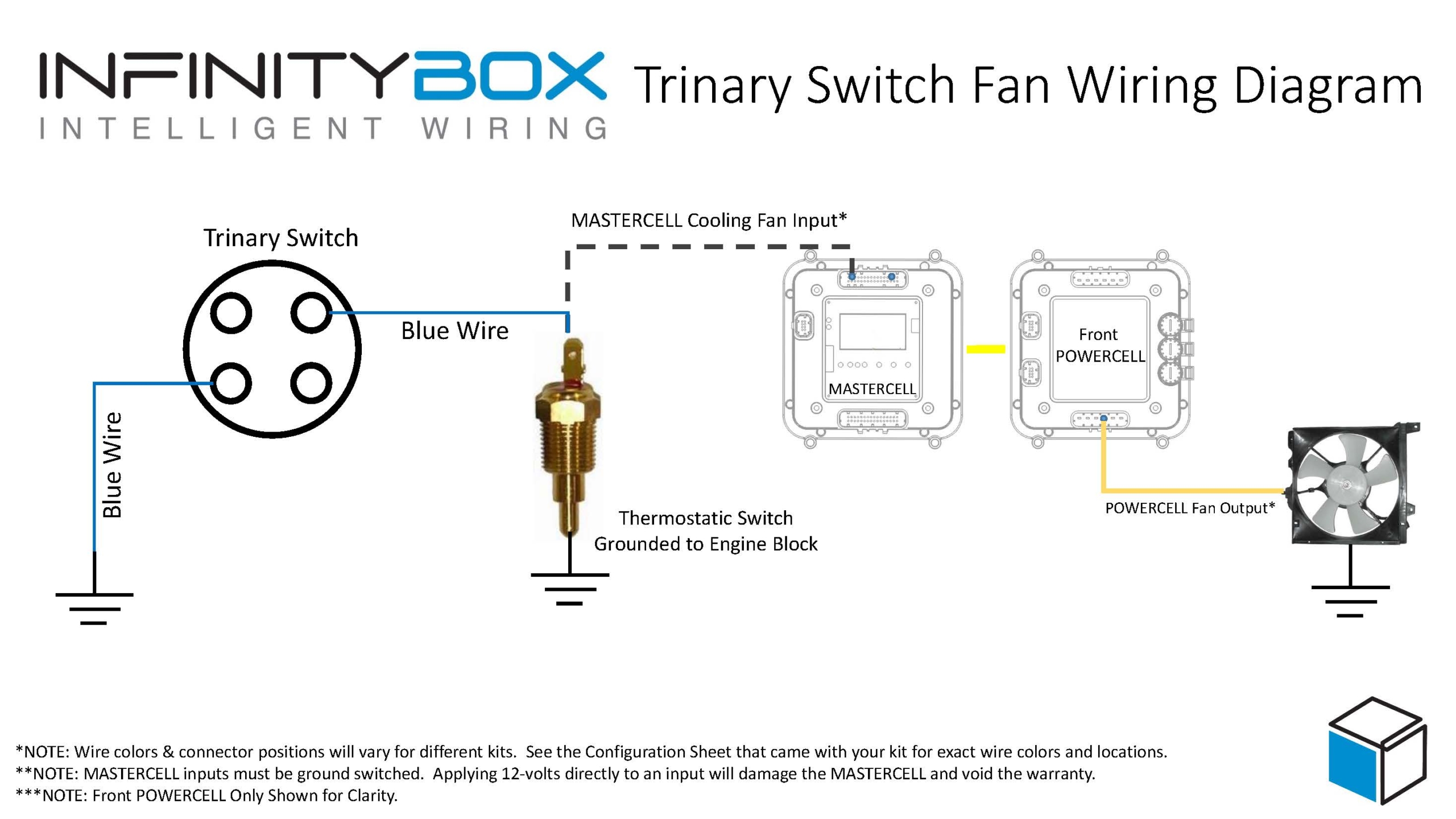
The last connections are for the cooling fan trigger. Connect the MASTERCELL input for your cooling fan to the FAN terminal on cavity 21 on the C1 connector. Note that you must add a blocking diode in series on this MASTERCELL input. Like the fuel pump input, this can be a 1N4001 diode. The orientation of this diode is critical for correct operation of the cooling fan. Check the wiring diagram for the proper orientation of this diode.
Once you have the MASTERCELL input wired for the cooling fan trigger, connect the cooling fan output from the front POWERCELL to your fan.
When the ECU sends the signal to turn on the cooling fan, the MASTERCELL input will get the trigger. The MASTERCELL will send a command to the front POWERCELL to turn on the cooling fan. This lets you eliminate the cooling fan relay in the AEM harness.
Please note that you must keep the EFI MAIN RELAY in the AEM harness. Follow their wiring instructions for this relay.
You can download a PDF of this wiring diagram by clicking this link.
You can contact one of our technical support engineers by clicking here if you have any questions about this wiring diagram or anything else related to wiring your car with our Infinitybox system.

 Copyright Infinitybox, LLC 2021. All Rights Reserved.
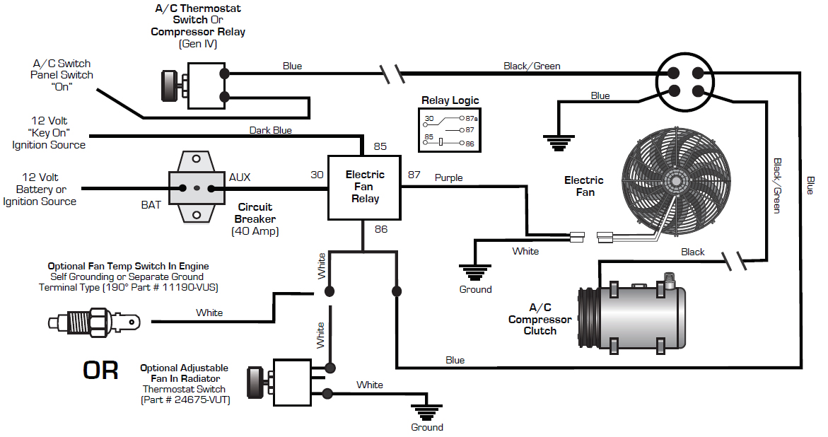
 Copyright Infinitybox, LLC 2021. All Rights Reserved.