 Copyright Infinitybox 2022. All Rights Reserved.
 Haltech ECU Wiring Diagram
Here’s the answer to a question that we get asked a lot. Will the Infinitybox system work with my ECU or EFI system? The answer is always, YES. We play nicely with everyone’s fuel injection system. We recently received this question related to the Haltech Elite 950 ECU. This blog post is going to show you how easy it is to wire this EFI set up with our Infinitybox system.
Just like anything else, please start by reading the instructions. This blog post is going to cover the details of wiring the Haltech Elite 950 ECU with the Infinitybox 20-Circuit Kit. We’re going to assume that you’re running our Front-Engine configuration. If you’re running our Rear-Engine configuration, check your configuration sheet for the specific locations of the inputs and outputs referenced in this blog post. The Haltech part number for this ECU is HT-150700 and you can get to its details at this link. Read and understand their instructions before you get into wiring.
This blog post is going to show you how to get ignition power to their ECU. It will also show you how to take the cooling fan and fuel pump triggers from the ECU into the MASTERCELL. Lastly, this blog post will show you how wire in the power to the injectors and coils so you can eliminate the need for external relays.
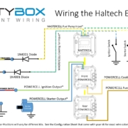
This diagram will show you the connections that you will make between your Infinitybox system and the Haltech ECU harness.
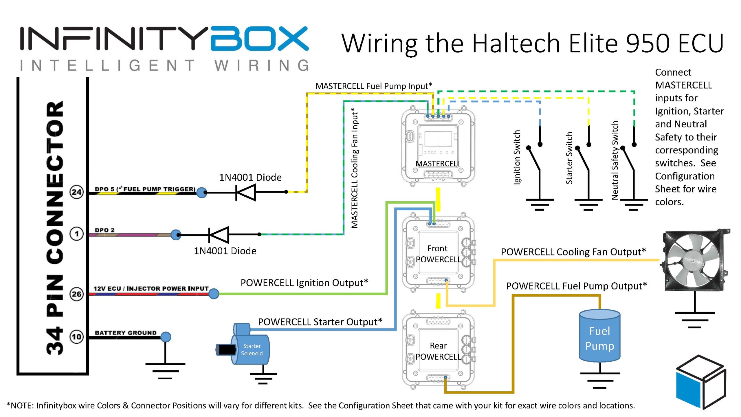
Haltech ECU Wiring Diagram with Infinitybox Control
To start, the ECU needs to be grounded. You need to take the black wire going to terminal 10 on the 34-pin connector and ground that. This should be through a metal-to-metal connection to the chassis. There should be no dirt, grease, oil, paint, rust, powder coating or anything else in this connection.
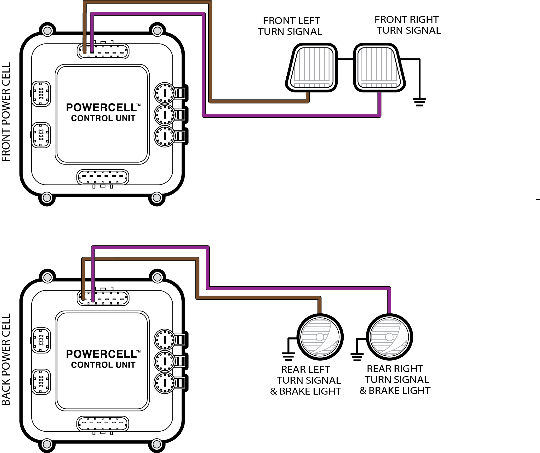
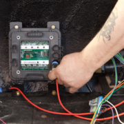
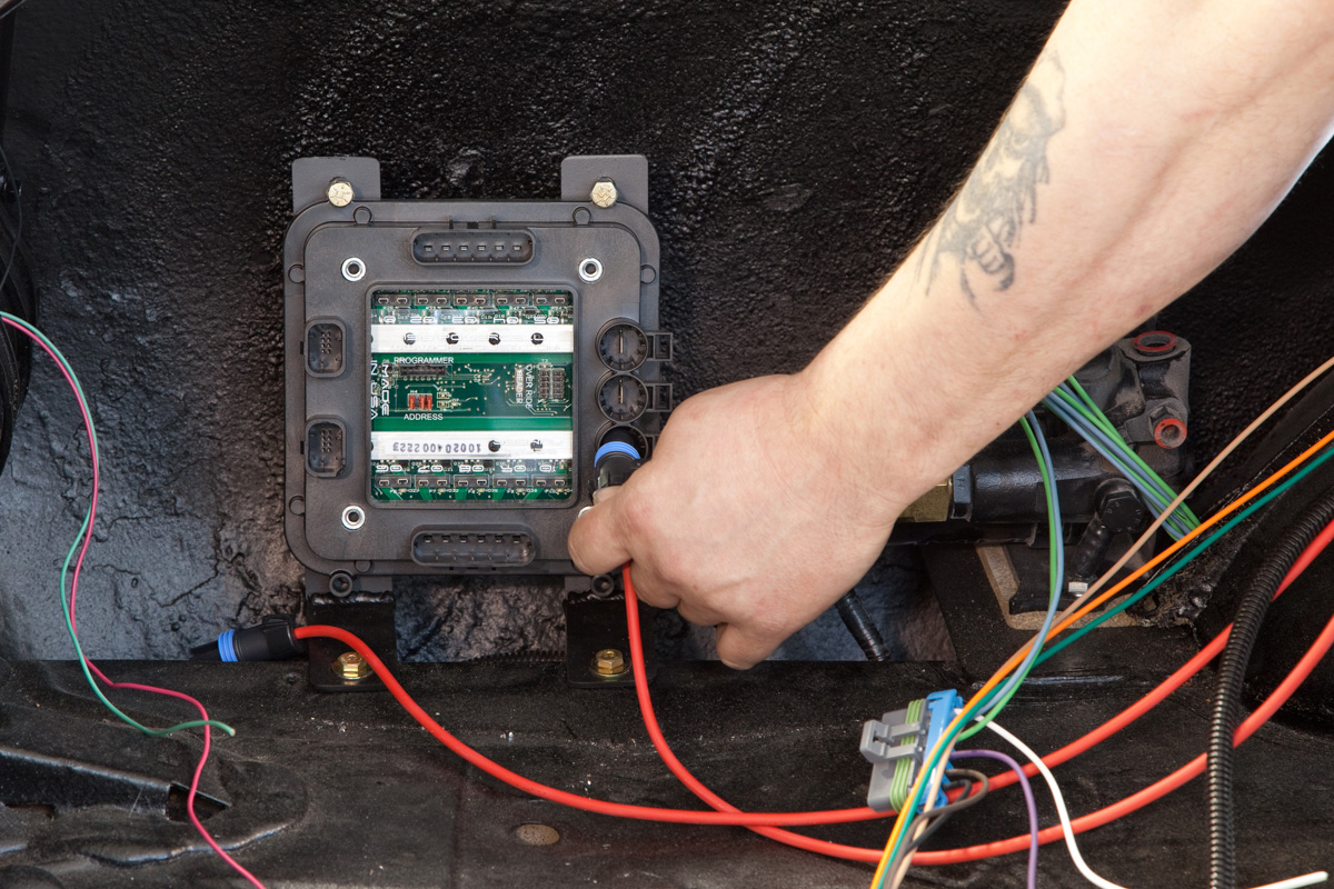
Next, the ECU needs key-on-power. This power should be on when the key is in the run and start position. You are going to get this power from the Ignition output on your POWERCELL. In most kits, this is output 3, the green wire, on the front POWERCELL. Check your configuration sheet for the wire colors for your specific kit. Since your POWERCELLs manage all of the high-current switching in your electrical system, you do not need external relays to control your fuel injection system. Connect your Ignition output from your POWERCELL to the “12V ECU” wire going to terminal 26 on the ECU harness. This is the red wire with the blue tracer.
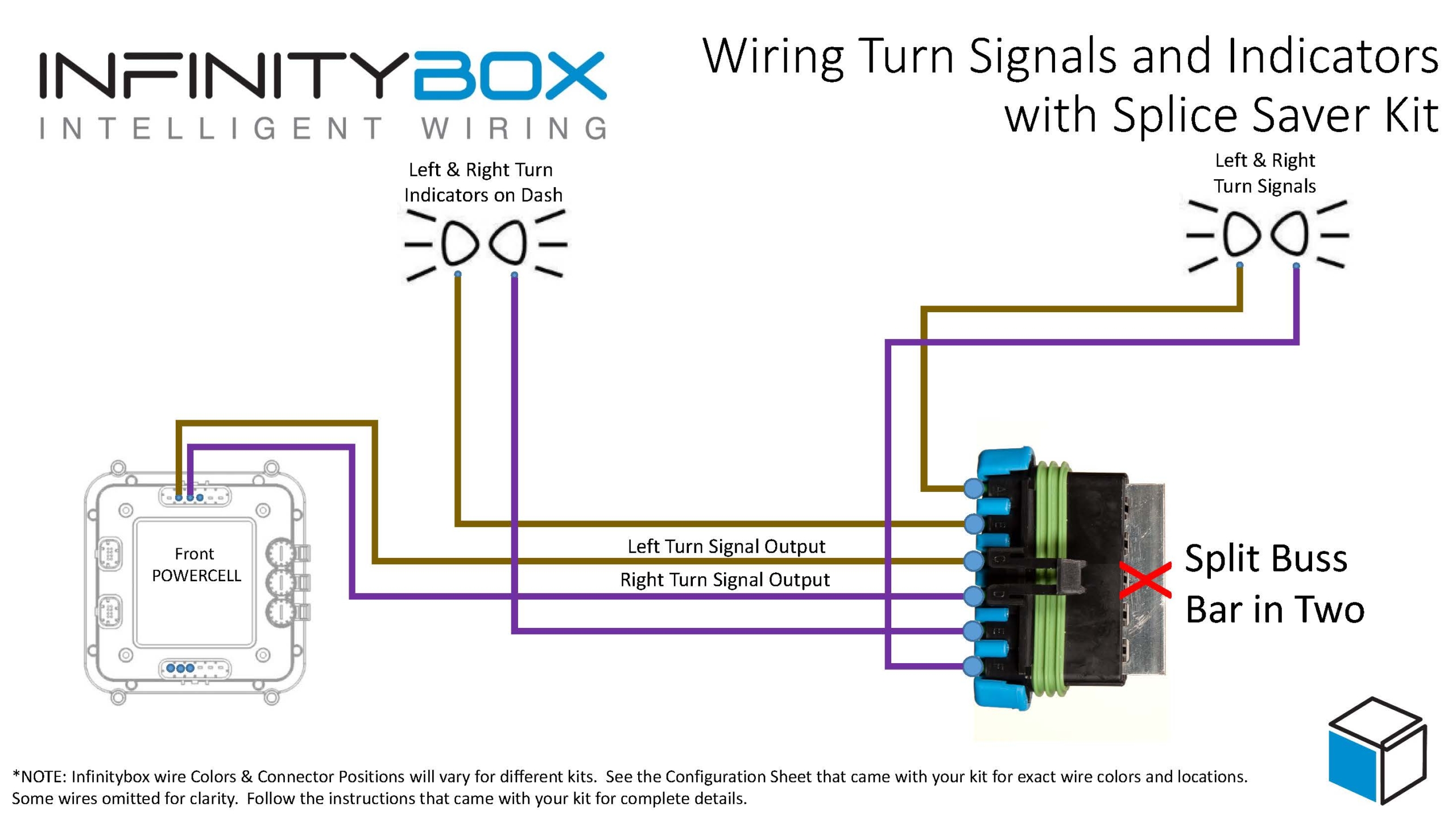
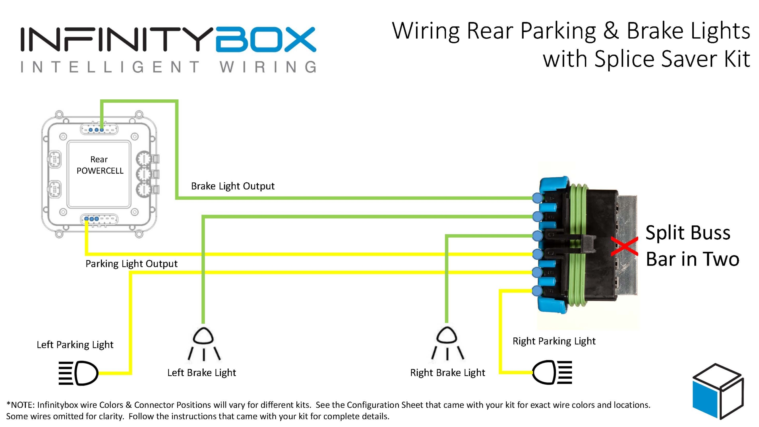
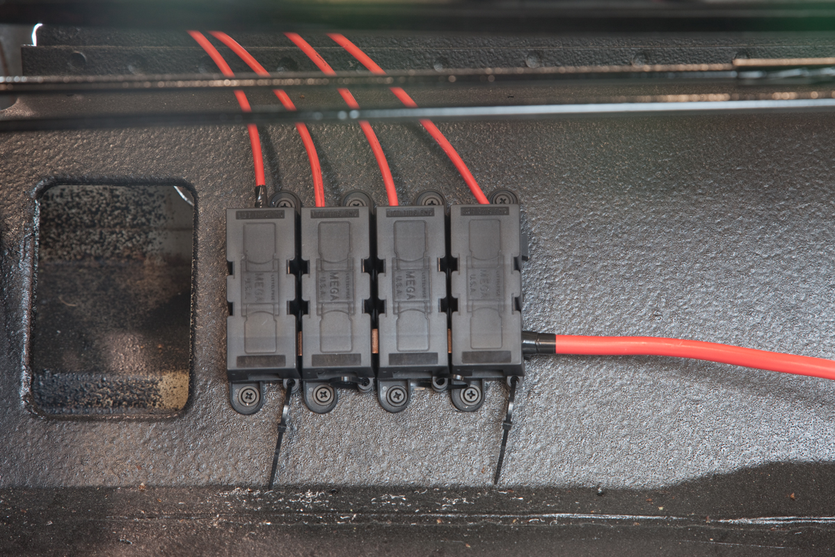
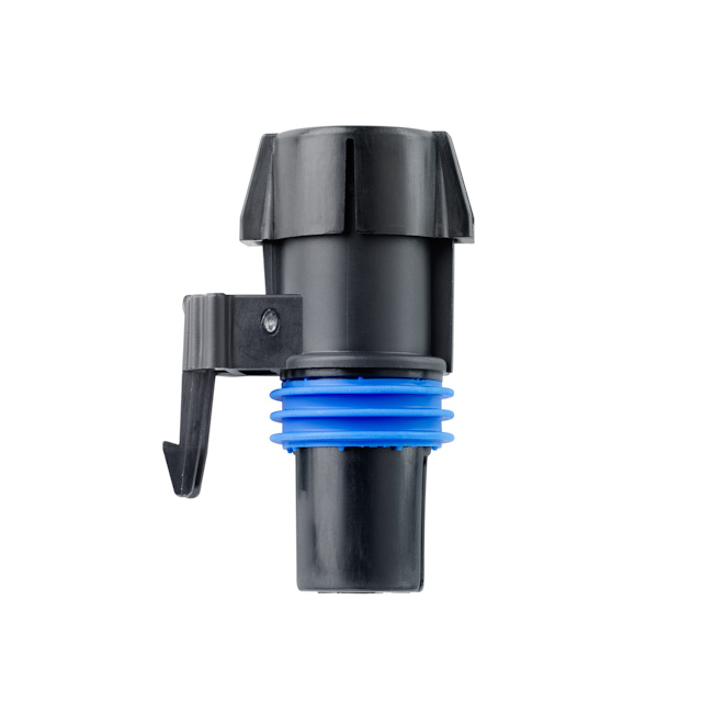
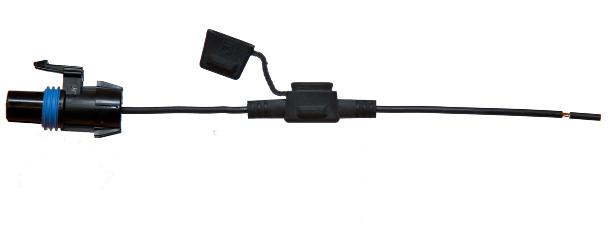
You can bring ignition power to the coils and the injectors from the Ignition output on your POWERCELL. You can splice these wire together, use a terminal block or use our Splice Saver kit to make a reliable and sealed connection. This diagram will show you how to connect the Splice Saver kit to your ignition output, the coils and the injector.
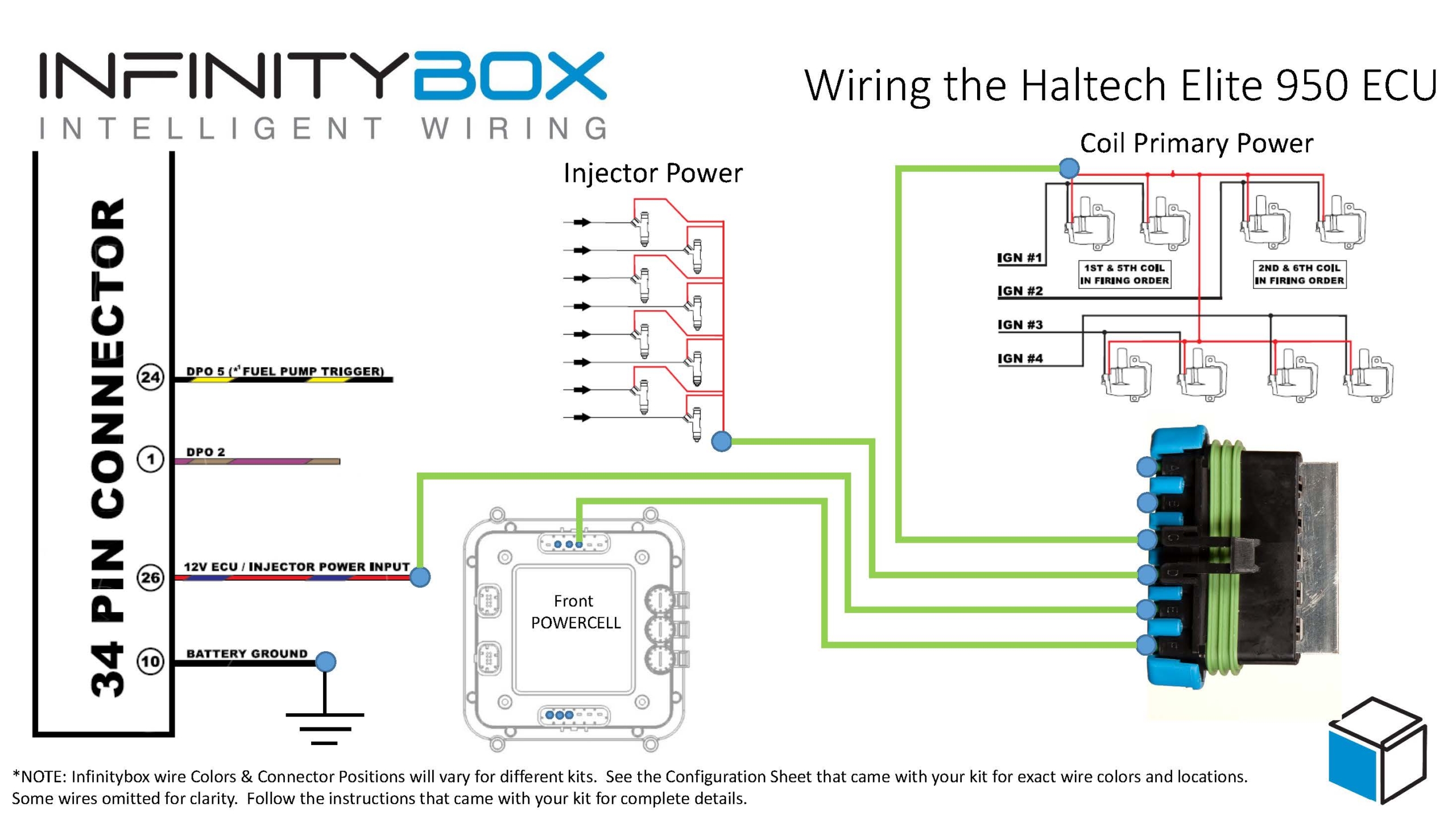
Infinitybox wiring diagram showing Haltech Key-On Power Wiring Details
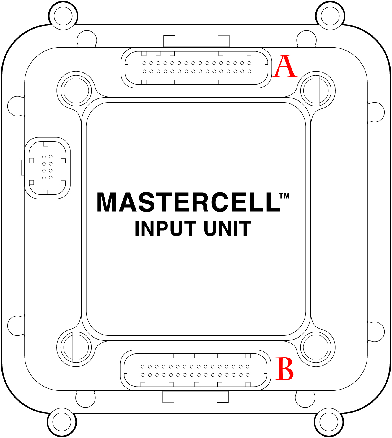
Next you are going to connect the outputs on the Haltech ECU for the fuel pump and the cooling fan to their inputs on the MASTERCELL. Haltech dedicates DPO 5 for the fuel pump. You can connect that to your MASTERCELL Input for your fuel pump. We strongly recommend isolating the MASTERCELL from the ECU with a 1N4001 diode. The orientation of this diode is very important. Refer to the diagram above to show proper orientation of the anode and cathode of this diode.
You can use any of the other digital outputs on the Haltech ECU to trigger the MASTERCELL input for the cooling fan. You must isolate the ECU from the MASTERCELL using a 1N4001 diode like the fuel pump. We chose DPO 2 in our diagram. You can use any of the available digital outputs however you must set them up correctly in their programming application.
Please note that you cannot pulse the DPO signal from the ECU that goes into the MASTERCELL for the fuel pump or the cooling fan. These should be on and off signals to turn the pump and fan on and off.
You can download a PDF version of our wiring diagram for the Haltech Elite 950 ECU by clicking this link.
You can contact our technical support team with any questions by clicking this link.
 Copyright Infinitybox, LLC 2021. All Rights Reserved.
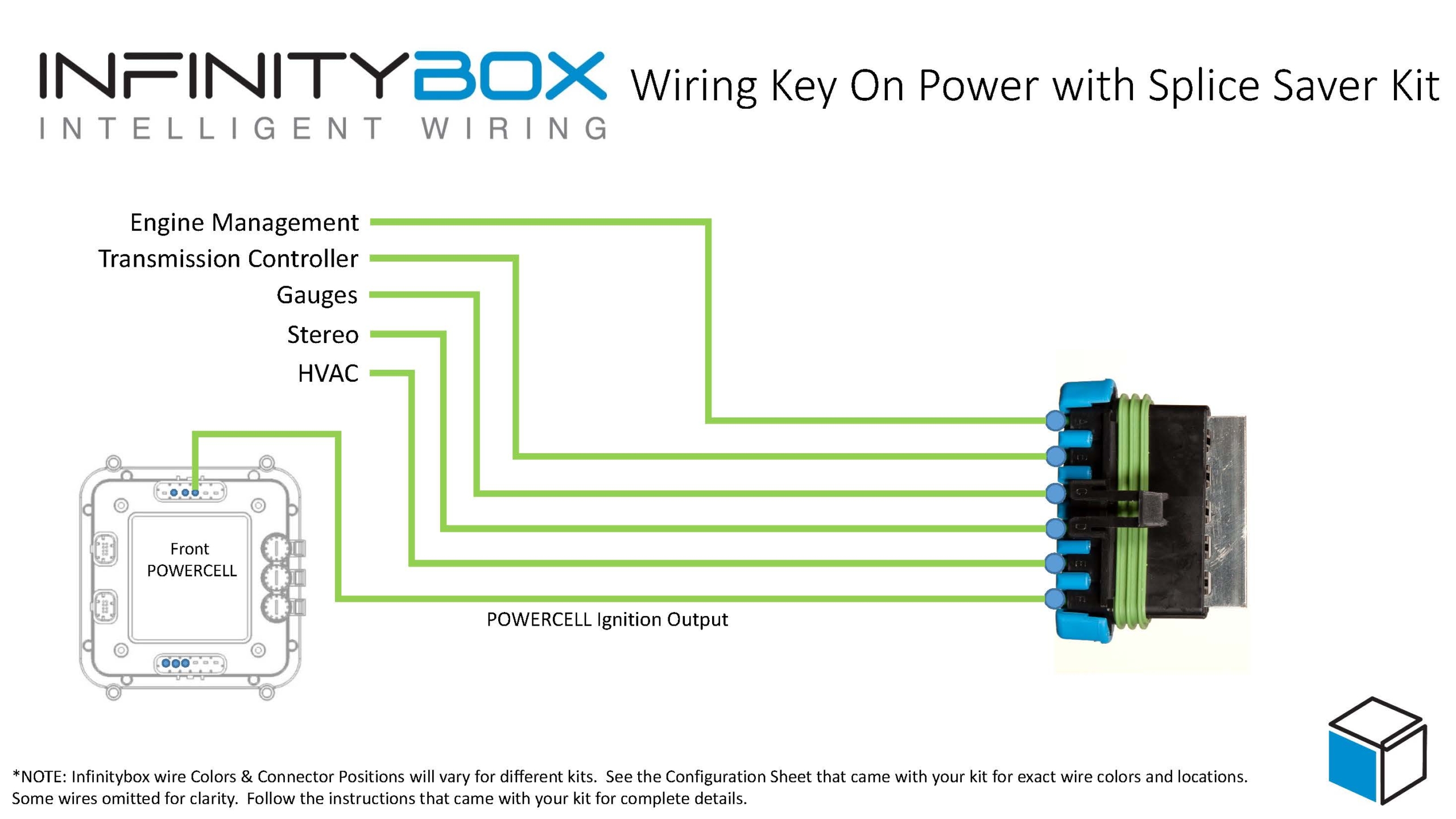
 Copyright Infinitybox, LLC 2021. All Rights Reserved.
  Copyright Infinitybox, LLC 2021. All Rights Reserved.
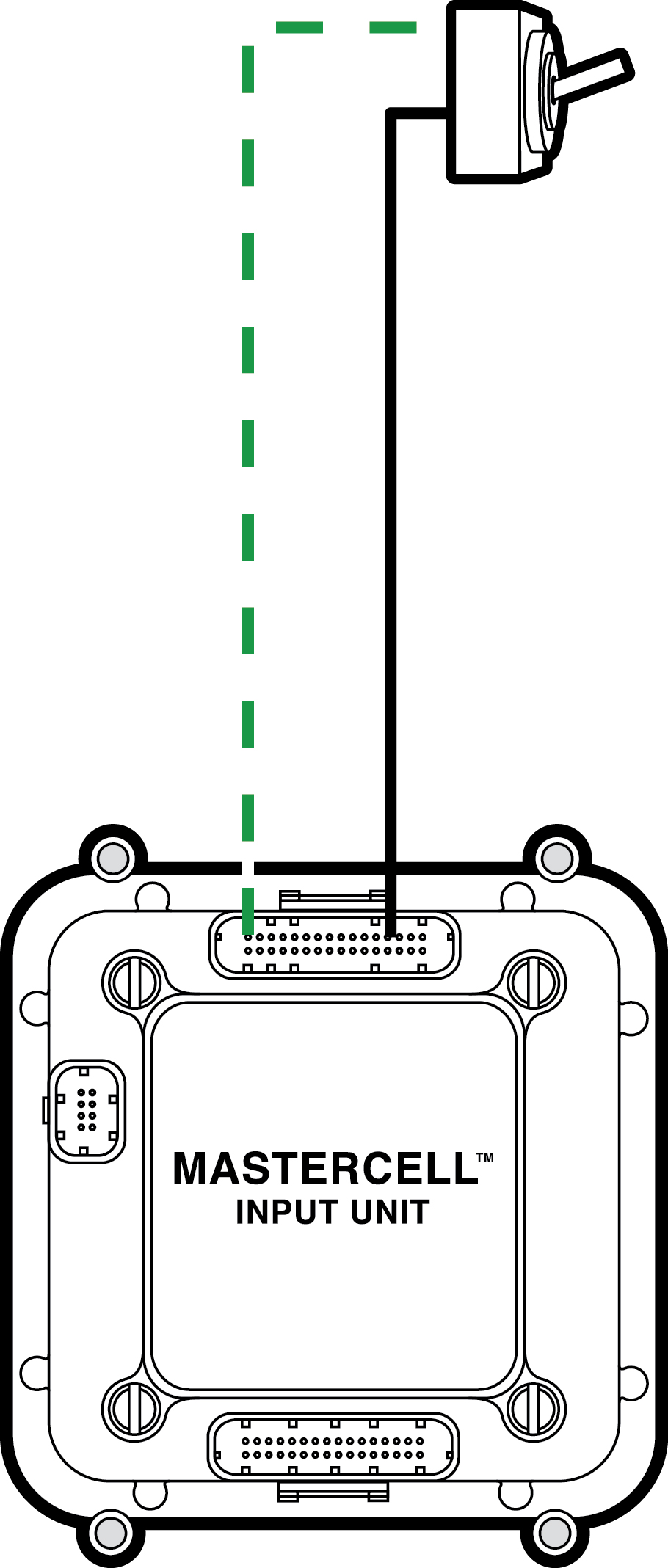
 Copyright Infinitybox, LLC 2021. All Rights Reserved.
 Copyright Infinitybox, LLC 2021. All Rights Reserved.
 Copyright Infinitybox, LLC 2021. All Rights Reserved.
 Copyright Infinitybox, LLC 2021. All Rights Reserved.