Speartech LS-58X
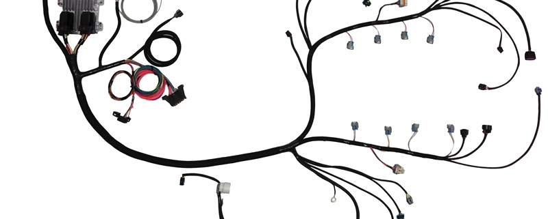
Our Infinitybox wiring system can interface with practically every engine management system in the aftermarket. This post is going to show you how to connect your 10 or 20-Circuit Kit to the Speartech LS-58X engine harness. LS swaps are one of the most popular transplants in resto-mods, street rods and Pro-Touring builds. Connecting your Infinitybox system to the Speartech LS-58X harness is pretty straight forward.
We get a lot of questions about how our Infinitybox wiring system connects to the ECU. We don’t control the engine. That is what the ECU does. We power the ECU. We can also take commands from the ECU to control external functions like the cooling fan and fuel pump.
In the case of the Speartech LS-58X engine harness, your Infinitybox system is going to provide the switched key-on ignition power. It will also take the triggers for the cooling fan and the fuel pump from the ECU. That way you can use the Infinitybox system to eliminate the need for external relays for your fuel pump and cooling fans.
Before you get any further, please read and understand the manual that came with your Speartech LS-58X harness. This link will take you to the wiring details from Speartech. Also, make sure you are familiar with your Infinitybox system.
In this post, we are only going to discuss connecting battery power, ignition power and the triggers for the cooling fan and fuel pump. Follow the Speartech instructions for the rest of the connections to your ECU and engine.
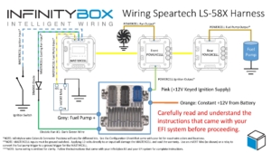
To begin, you have to connect the Orange wire in the Speartech harness directly to your battery. Follow their instructions for proper connections and proper fuse sizes to protect this wire.
Next, you need to connect the ignition output from your POWERCELL to the Pink wire in the Speartech LS-58X harness. This is ignition power from the POWERCELL. When you turn the key to the ignition position, you will get battery voltage to the ECU.
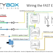
Next, connect the Grey Fuel Pump + wire from the Speartech harness to the MASTERCELL. This is a positive trigger for the fuel pump so it must be inverted to a ground signal to connect to the MASTERCELL input. You can use one of our inVERT Minis to do this. Alternately, you can use a relay to invert this signal. Click on this link to learn how to use a relay to do this. You must not connect the MASTERCELL input directly to the Fuel Pump Trigger from the Speartech harness. This will damage your MASTERCELL input and void the warranty. Check your configuration sheet for the exact wire colors for your fuel pump trigger.
Last, you need to connect your cooling fan trigger from the MASTERCELL to the Speartech harness. Check your configuration sheet for the wire colors for your cooling fan input. The Speartech ECU ground triggers the cooling fan outputs. That means that you can connect the MASTERCELL input wire directly to the Speartech harness. The primary cooling trigger from Speartech is the Dark Green wire in their harness.
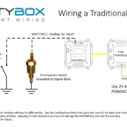
We strongly recommend soldering a 1N4001 diode in between the MASTERCELL input wire and the EFI system trigger wire for the cooling fan. This isolates the MASTERCELL from the EFI system. Diodes are directional parts so you must wire them with the cathode side facing towards the ECU. That is the side of the diode that has the stripe on it.
The Speartech LS-58X harness has provisions to control two cooling fans. You can use any OPEN POWERCELL output on your system to control your second cooling fan with the Speartech harness. Wire the Dark Green wire from the Speartech harness, through the diode as described above, to the MASTERCELL input wire for your second cooling fan. This way, the Speartech harness will control your primary and secondary cooling fans through your Infinitybox system without having to add relays.
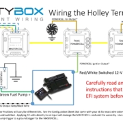
This picture shows the details of wiring the Infinitybox System to the Speartech LS-58X Engine Harness. Please note that Infinitybox wire colors may vary based on different configurations. See the configuration sheet that came with your kit for the specific wire colors.
You can download a PDF version of this wiring diagram by clicking this link.

 Copyright Infinitybox 2022. All Rights Reserved.
 Copyright Infinitybox, LLC 2021. All Rights Reserved.
  Copyright Infinitybox, LLC 2021. All Rights Reserved.
 Copyright Infinitybox, LLC 2021. All Rights Reserved.
 Copyright Infinitybox, LLC 2021. All Rights Reserved.
  Copyright Infinitybox, LLC 2021. All Rights Reserved.
Leave a Reply
Want to join the discussion?Feel free to contribute!