Options for Touch Screen Control
When we introduced our inTOUCH NET product in 2013, it gave our customers a very simple way to use a smart device to control all of the electrical functions in their hot rods, street rods, resto mods, kit cars and Pro-Touring builds. Any smart phone or tablet seamlessly connects with inTOUCH NET to give you touch screen control of your lighting, ignition, starter, locks, windows, accessories and your heating & air conditioning controls. inTOUCH NET is very flexible. It can connect with any device that has a touch screen, a browser and Wi-Fi. You can learn more about how inTOUCH NET works by clicking this link. This blog post is going to go through other options for touch screen control of your car’s electrical system using our inTOUCH NET. There is a very detailed video below that walks you through the process step by step.
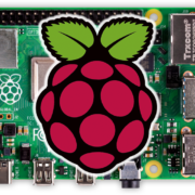
This option uses a Raspberry Pi and a HMDI touch screen. Both of these parts are easy to get, simple to set up and give you great flexibility. The Raspberry Pi is small and simple to hide behind your dash. You have tons of options for different sizes of touch screens and they are all easy to mount in a dash.
The Raspberry Pi is easy to get. You can buy these directly from their website by clicking this link. You can also get them from other on-line sources like Amazon. Be sure to get the Raspberry Pi 4 because this is the version that has Wi-Fi built into it. There are multiple memory size options for the Raspberry Pi. For this project, you can use the smallest 2Gb option.
Next, you need a screen to mate with the Rasbperry Pi. If you search Amazon for “Raspberry Pi touchscreen”, you’ll get a ton of options ranging from 4.3″ to 12″ diagonal screens. You can pick the size that fits your dash. You need to find a screen that has HDMI and USB. The Raspberry is going to send out the video signal over HDMI. The touch signals and the power for the screen will come from the USB connection. This link will take you to the screen that we used in the video below.
Lastly, you will need a micro-SD card to hold the operating system for the Raspberry Pi. Anything larger that 2Gb will work. This link will take you to the card that we used in the video below.
This video walks through the steps to set this up.
First, you need to connect the Raspberry Pi to the touch screen. There are two connections: the HDMI cable for video and the USB cable for power and touch screen commands. You also need to get power to the Raspberry Pi. That comes in through a USB C cable. You need to get a place behind your dash to plug in the USB C cable. A USB port like this one will convert your car’s battery voltage to the required 5-volts for the USB cable.
Next, you need to load the Raspian operating system on the Micro-SD card. The video goes through that in detail. This link will take you to the place to download Raspian.
Lastly, you need to connect the Raspberry Pi to the Wi-Fi broadcast by the inTOUCH NET. The video below goes through the details but you can also watch this video to learn more about the process.
Check out the full set up video here.
Once you’ve gone through these steps, you have a touch screen interface that you can mount in your dash to control your entire electrical system through the Infinitybox inTOUCH NET. This shows you the options for touch screen control with the Infinitybox system.
Click on this link to contact our technical support team with any questions.
 Copyright Infinitybox, LLC 2021. All Rights Reserved.
 Copyright Infinitybox, LLC 2021. All Rights Reserved.
  Copyright Infinitybox, LLC 2021. All Rights Reserved.
  Copyright Infinitybox, LLC 2021. All Rights Reserved.
  Copyright Infinitybox, LLC 2021. All Rights Reserved.
 Copyright Infinitybox, LLC 2021. All Rights Reserved.
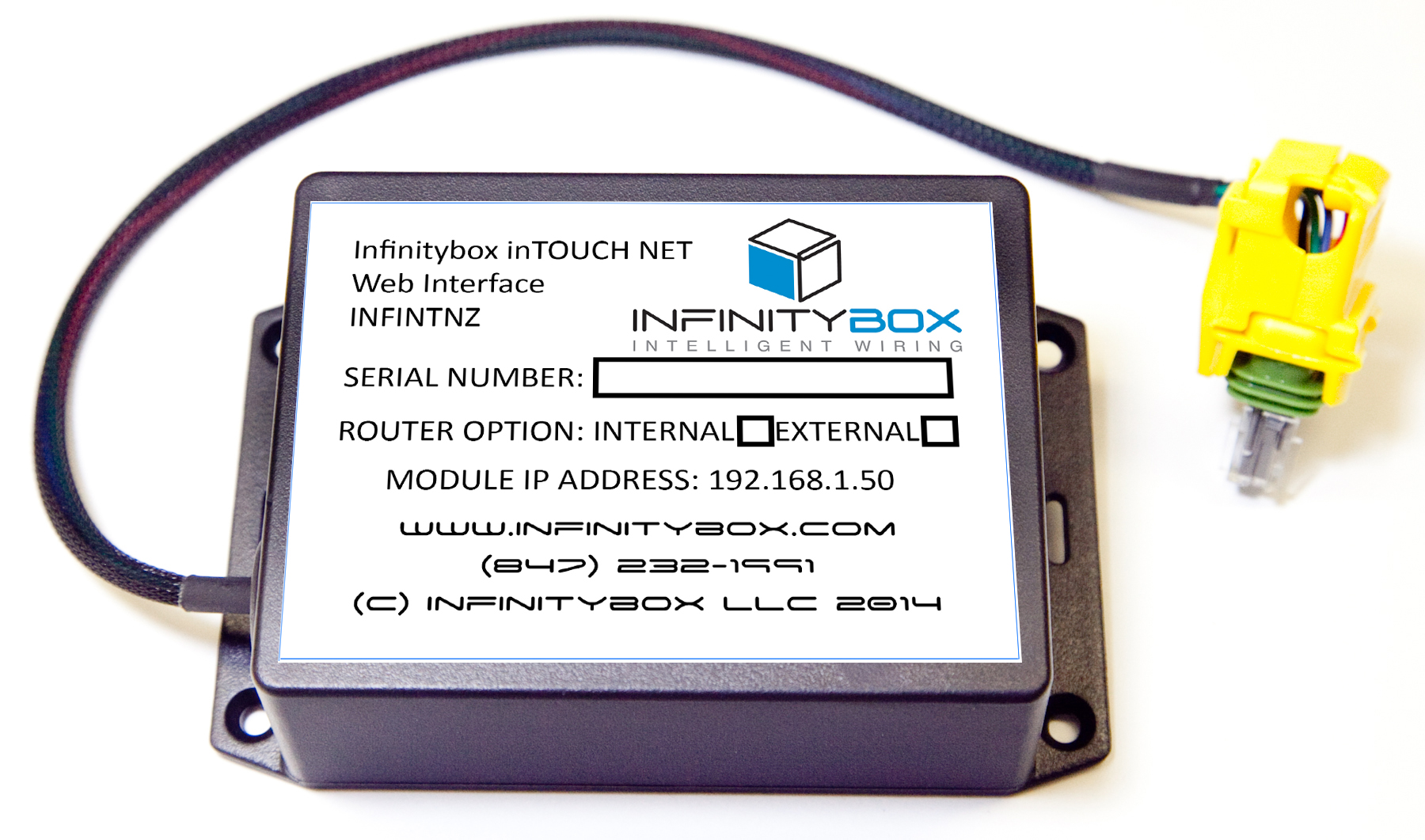
 Copyright Infinitybox, LLC 2021. All Rights Reserved.

