Posts

Picture of the IDIDIT id.TOUCH System

Wiring the IDIDIT idTOUCH

This blog post is going to show you how to wire the IDIDIT id.TOUCH PKE system to the Infinitybox 20-Circuit Kit.  The Infinitybox system is the electrical backbone for your restoration, resto-mod, street rod, kit car, or Pro-Touring build.  Our system is flexible enough to connect and power any external electrical accessory that you want to add.  In the case of wiring the IDIDIT id.TOUCH, your 20-Circuit Kit is already powering your ignition, starter solenoid and accessories.  You are going to use the id.TOUCH as the switches that connect to the MASTERCELL to control these functions.  Keep reading to learn more.

Before we go to far, please carefully read and understand all of the instructions that came with your IDIDIT id.TOUCH system.  You can access the manual from the IDIDIT website by clicking this link.  This blog post is only going to cover the wiring and connections related to the Infinitybox system.  Please follow their instructions for the complete wiring.

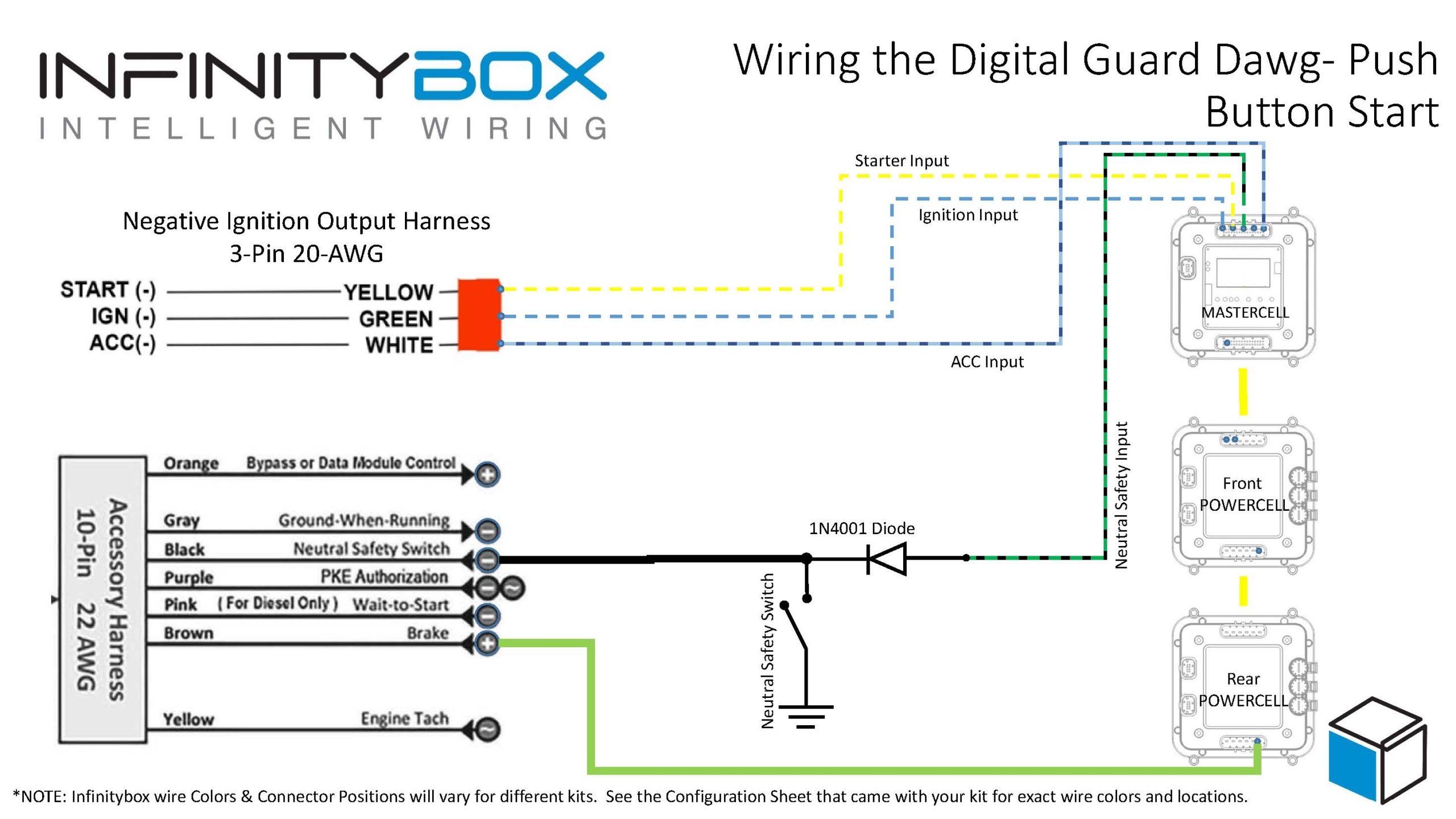
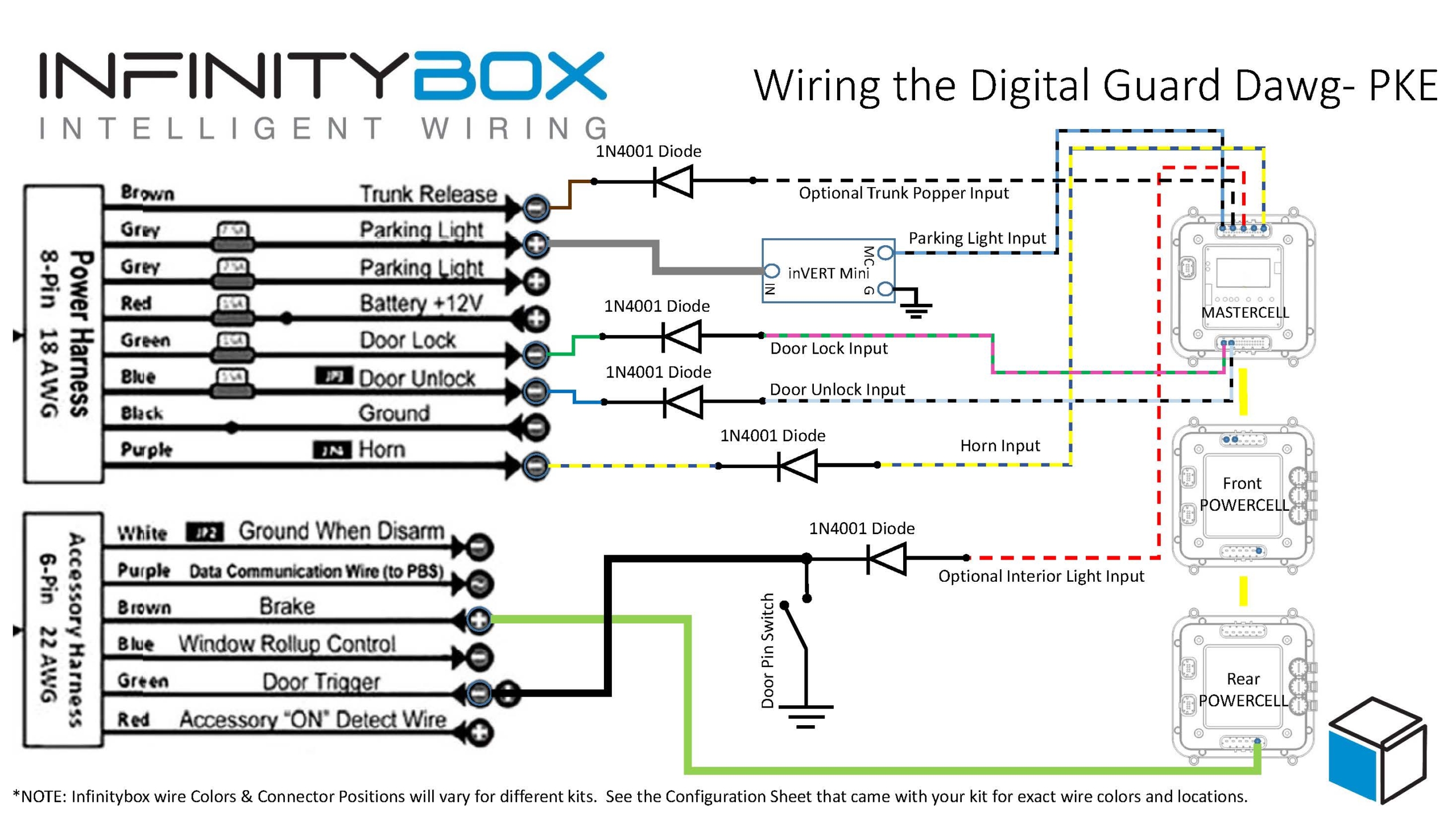
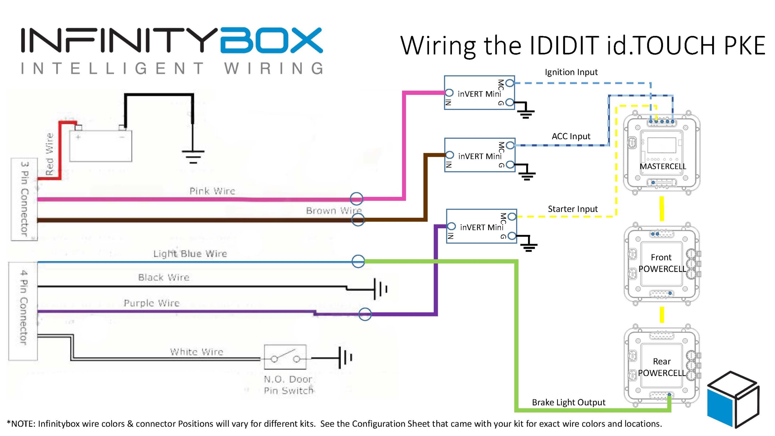
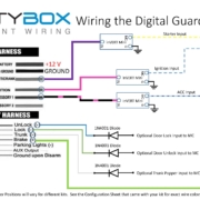
Wiring the IDIDIT id.TOUCH to the Infinitybox 20-Circuit Kit is pretty easy.  To the MASTERCELL, the id.TOUCH is just going to look like any ignition & starter switch.  This wiring diagram shows the details.

Picture of the wiring diagram showing the optional outputs from the IDIDIT id.TOUCH and the Infinitybox system

Picture of the wiring diagram showing the optional outputs from the IDIDIT id.TOUCH and the Infinitybox system

The connections that you are concerned about are the id.TOUCH outputs for the ignition, starter solenoid and the accessories.  You also need to wire the id.TOUCH input for the brake pedal signal.

For the id.TOUCH outputs for the ignition, starter solenoid and accessories, these are positive 12-volt signals.  Our MASTERCELL needs ground triggers.  Do not wire the outputs from the id.TOUCH directly to the MASTERCELL inputs.  This can potentially damage the MASTERCELL and will void your warranty.  You need to either use a small relay to invert these signals or use our inVERT  Minis.  The wiring diagram shows the correct wiring of the inVERT Mini.

Check the configuration sheet that came with your Infinitybox 20-Circuit for the correct wire colors for the inputs and outputs mentioned in this blog post.  You can learn more about the configuration sheet at this link.

The diagram from IDIDIT shows a neutral safety switch on the purple wire going to the starter solenoid.  You do not need to wire this with the Infinitybox system.  There is a separate neutral safety input that goes to the MASTERCELL.  See this link for more details.

The id.TOUCH has an accessory output wire on it.  That can be wired to the MASTERCELL to control any of the OPEN outputs on the system.  This can be used to control an output separate from the ignition to power your stereo or anything else that you want separate from the ignition.

You also need to connect the POWERCELL brake light output to the brake pedal input on the id.TOUCH.  The id.TOUCH needs a positive 12-volt signal to know that you foot is on the brake pedal.

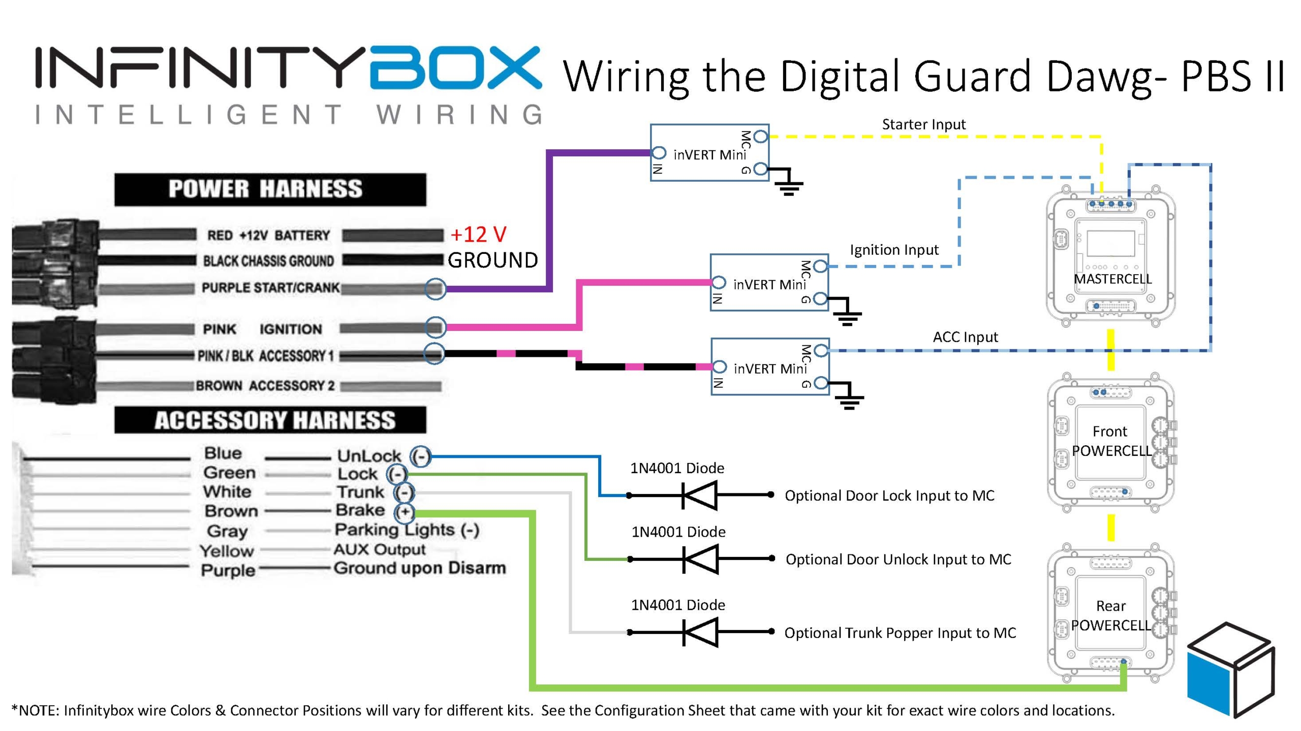
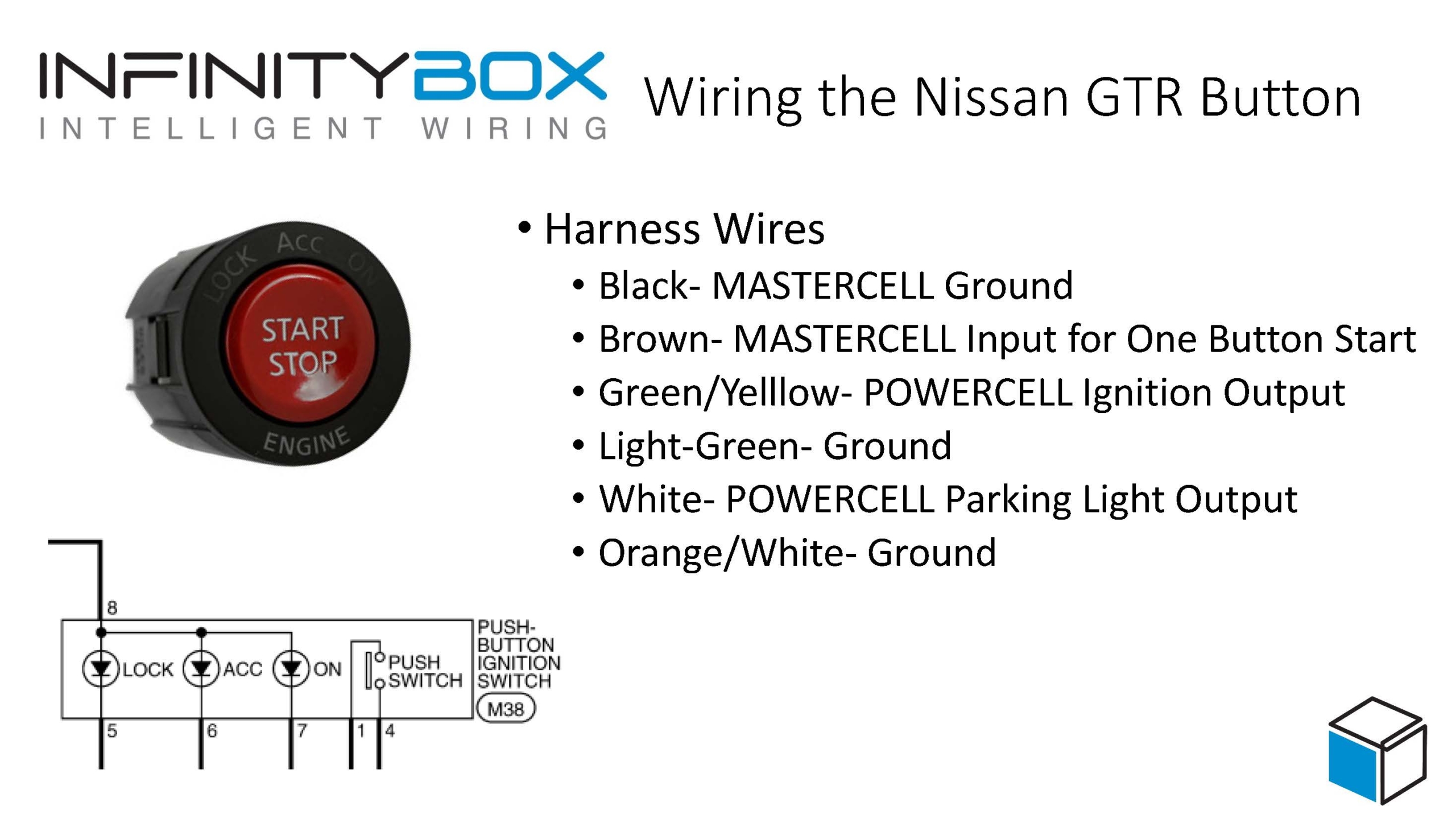
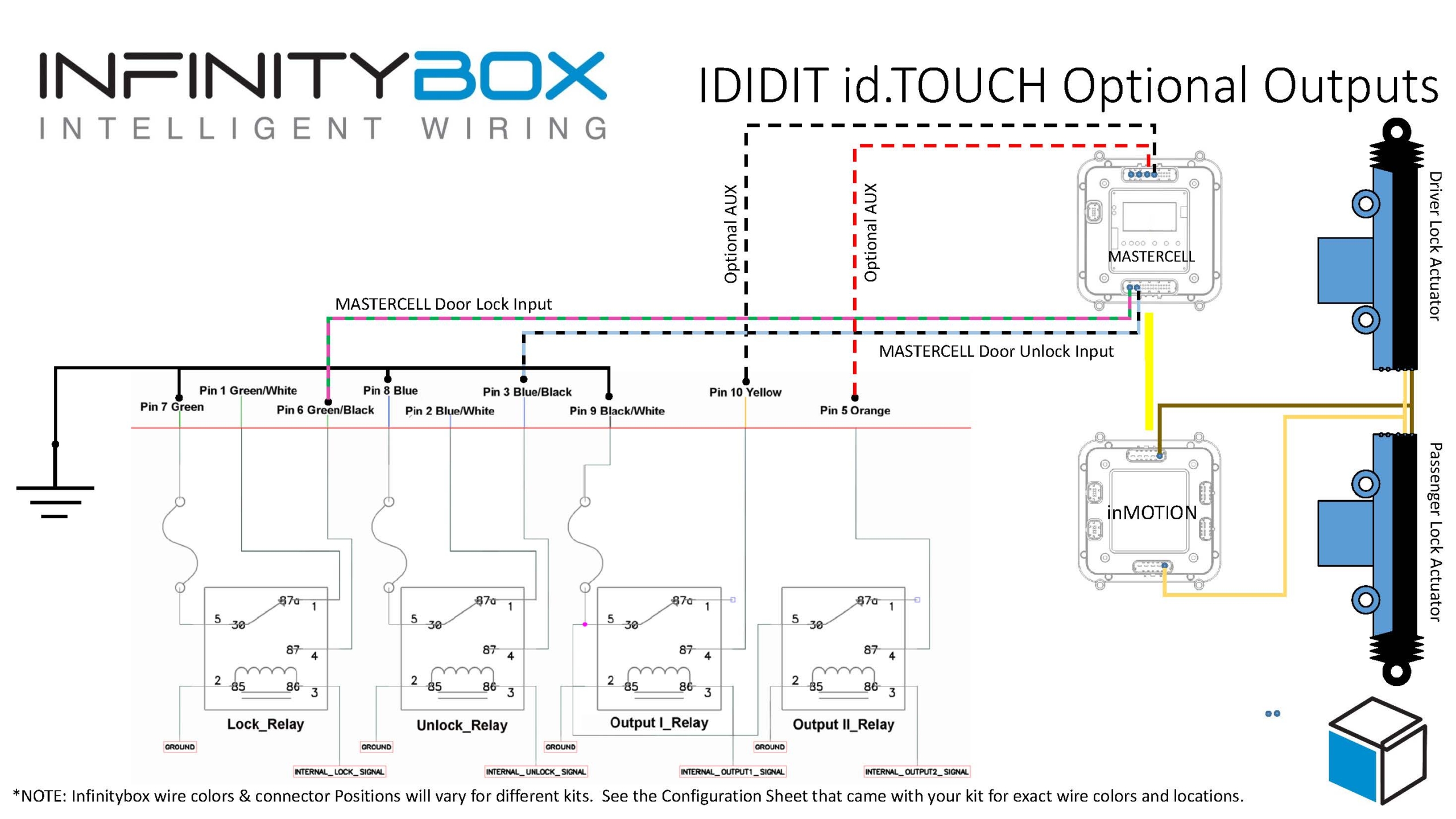
Once you have the ignition, starter solenoid and accessories controlled by your IDIDIT id.TOUCH, you can add more optional features.  The id.TOUCH has a set of relays built in that can be used to control optional functions in the car.  For example, you could add a trunk popper.  Or you could control your door locks if you have our inMOTION cell as part of your Infinitybox system.  See the id.TOUCH manual for more details about setting this up.  This diagram shows how to wire the optional functions on the id.TOUCH to your MASTERCELL inputs.

Picture of the wiring diagram showing the PKE outputs from the IDIDIT id.TOUCH and the Infinitybox system

Picture of the wiring diagram showing the PKE outputs from the IDIDIT id.TOUCH and the Infinitybox system

The optional control relays on the id.TOUCH are not connected to power or ground, which makes wiring them very easy.  You simply need to ground the Green, Blue and Black/Wires in the optional harness.  The MASTERCELL inputs for lock and unlock on inMOTION would connect to the Green/Black and Blue/Black wires, respectively.  Any additional MASTERCELL inputs for accessories would connect to the Yellow and Orange wires.

The combination of the Infinitybox 20-Circuit Kit and the IDIDIT id.TOUCH gives you modern functionality in your restoration, restomod, street rod, kit car or Pro-Touring build.  You can download a PDF of these wiring diagrams by clicking this link.

Click on this link to contact our technical support team with any questions about these wiring diagrams.

Digital Guard Dawg PBS II Wiring

Picture of the Digital Guard Dawg PBSII System

Picture of the Digital Guard Dawg PBSII System

Our Infinitybox system plays nicely with any other electrical accessory that you would want to install in your hot rod, restoration, resto-mod, street rod, kit car or pro-touring build.  This blog post is going to cover the Digital Guard Dawg PBS II wiring.  It will show you how to connect the PBS II push-button start PKE module to your Infinitybox 20-Circuit Kit.  This gets you the passive keyless entry features of the Digital Guard Dawg PBS II paired with the power and flexibility of the Infinitybox system.  We have blogged before about wiring their iKey system into our Infinitybox system.  You can see that post by clicking this link.

Before you go anywhere, it is very important that you thoroughly read and understand the manual for the Digital Guard Dawg PBS II.  You can access that by clicking this link.  Once you are familiar with their instructions, it is time to get into the Digital Guard Dawg PBS II wiring and the Infinitybox system.  This blog post is only going to cover the connections between the PBS II and the Infinitybox system.  Follow their instructions for all constant power and ground connects.  Also follow their instructions for wiring their push to start button and their training button.

The PBS II will give you passive keyless entry (PKE) capability for your car.  As you approach the car, the PBS II system detects the presence of the key fob in your pocket.  It engages the ignition and lets you start the car.  The PBS II connects to the MASTERCELL of your 20-Circuit Kit and replaces the need for a traditional ignition/start switch.  This diagram shows the necessary connections that you need to make.

Picture of Infinitybox wiring diagram showing to to wire the Digital Guard Dawg PBSII

Picture of Infinitybox wiring diagram showing to to wire the Digital Guard Dawg PBSII

The PBS II will send the signals to the MASTERCELL for the ignition and the starter.  When the MASTERCELL sees these inputs turn on, it will send the required signals to the POWERCELLs to power your ignition and starter outputs.  The PBS II wires for the ignition and starter are positive signals.  The MASTERCELL requires ground triggers for the inputs so you will need to wire in our inVERT Minis to buffer their positive signal.  You can learn more about the inVERT Mini and purchase them at this link.  The diagram above shows where to put the inVERT Minis in the circuit.

The PBS II also needs a signal to know that you are stepping on the brake pedal.  This signal must be positive 12-volts.  Since our MASTERCELL inputs work by being triggered to ground, you cannot get this positive brake signal from the brake pedal switch directly.  You need to get this from the POWERCELL output for the brake lights.  You can simply splice into the brake light output on the rear POWERCELL.  Alternately, you can use an OPEN output on the front POWERCELL as the brake pedal trigger.  You would wire the corresponding input to your OPEN output to the brake pedal switch, in parallel with your usual brake light input.  Doing it this way keeps the run of wires in the car short.

The PBS II also has provisions to control door locks and trunk poppers.  If you purchased inMOTION for your Infinitybox system, you can wire the MASTERCELL inputs for your door locks to the Unlock and Lock signals on the PBS II Accessory Harness.  We recommend using a diode to isolate the MASTERCELL from any stray voltages that may exist in the PBS II.  This diode should be a 1N4001 and must be oriented per the diagram above.  These inputs will not work if the diodes are installed incorrectly.

The PBS II also has provisions to control a trunk popper from their key fob.  You can take any of the OPEN outputs on your rear POWERCELL to control you trunk popper.  You would wire the corresponding MASTERCELL input to the white Trunk wire in their accessory harness.  Just like the signals for the door locks, we recommend isolating the MASTERCELL inputs from the PBS II with a 1N4001 diode as shown in the wiring diagram.

You can download a PDF version of this wiring diagram by clicking this link.

Please contact our team if you have any questions about this Digital Guard Dawg PBS II Wiring diagram.  You can reach out team by clicking this link.

Picture of the Digital Guard Dawg iKEY System

Digital Guard Dawg iKEY

We always say that our Infinitybox system plays nicely with any other piece of automotive electronics.  We have our own remote keyless entry system with inLINK and our one-button start feature is built into all of our 10 and 20-Circuit Kits.  Some of our customers like to use  push-button start feature and Passive Key Less Entry (PKE) system manufactured by other companies.  This post will go through the details of connecting the Digital Guard Dawg iKEY system to the Infinitybox system.

Before we go any further, you must thoroughly read and completely understand the manuals that come with your Digital Guard Dawg iKEY system.  In the case of this system, there are two manuals.  One for the push-button start module and one for the PKE module.  This blog post is only going to describe how to connect the wires that are relevant to the Infinitybox system.  Carefully follow the instructions for all of the other connections to their harnesses including power and ground.

By connecting the Digital Guard Dawg iKEY to the Infinitybox system, you get all of the advantages of Infinitybox plus the PKE features of the iKEY system.  The iKEY system has several outputs that are +12 volts and ground switched.  The Infinitybox MASTERCELLs work on ground signals.  You will need to use our inVERT Mini‘s to connect the +12 volt outputs to the MASTERCELL inputs.  Failure to do so will damage the inputs on the MASTERCELL and will void your warranty.  Also, you must use a diode to isolate the ground outputs on the Digital Guard Dawg iKEY from the MASTERCELL inputs.  Failure to do this could result in damage to the inputs and will void your warranty.  You can use a 1N4001 diode easily sourced from any electronics store.  Also note that the orientation of the diode is critical.  Please pay attention to this in the wiring diagrams.

Please note that the wire colors and connector locations shown in the following diagrams may not match your system exactly.  We have several different configurations.  Please reference the configuration sheet that came with your kit for the exact wire colors and connector locations.

The following diagram shows you how to connect the Push-Button Start module to the MASTERCELL inputs and POWERCELL outputs of your Infinitybox system.

Picture of the wiring diagram showing the Digital Guard Dawg Push Button Start Wiring with the Infinitybox System

Picture of the wiring diagram showing the Digital Guard Dawg Push Button Start Wiring with the Infinitybox System

Here are the details:

  1. Digital Guard Dawg has a dedicated harness with Negative Ignition Outputs designed to work with our Infinitybox system.  You can use this harness to connect directly to the MASTERCELL inputs for the Ignition, Starter and Accessory.  The yellow wire in their harness connects to your starter input.  The green wire connects to your ignition input and their white wire connects to your accessory input.
  2. Connect the Black wire from the accessory harness to the neutral safety or clutch interlock switch.  This is the same switch used for the neutral safety input going to the MASTERCELL.  Be sure to wire in the diode to isolate the MASTERCELL input from the Push-Button Start module.
  3. Tap off of the brake light output on your rear POWERCELL and connect that to the Brown wire on your accessory harness.

This diagram will show you how to wire the PKE module to the Infinitybox system.

Picture of the wiring diagram showing the Digital Guard Dawg PKE Wiring with the Infinitybox System

Picture of the wiring diagram showing the Digital Guard Dawg PKE Wiring with the Infinitybox System

Here are the details.

  1. Connect the Brown wire on the power harness through a diode to an optional input for a trunk popper.  Not all of our systems may be set up for this feature.  Your system may need to be updated to add this.
  2. Connect one of the Grey wires from the power harness to an inVERT Mini.  Tap into the MASTERCELL input for the parking light and connect that to the MASTERCELL side of the inVERT Mini.
  3. Connect the Green and Blue wires from the power harness to the optional inputs for door lock and unlock.  You need to have inMOTION for this option to work.  The MASTERCELL inputs must be isolated from the PKE module by diodes as shown in the drawing.
  4. Connect the Purple wire from the power harness to your MASTERCELL input for the horn through a diode.
  5. Connect the Green wire from the accessory harness to the pin switches on your doors.  This is the same switch used for the interior lights input going to the MASTERCELL.  Be sure to wire in the diode to isolate the MASTERCELL input from the Push-Button Start module.
  6. Tap off of the brake light output on your rear POWERCELL and connect that to the Brown wire on your accessory harness.

You can download a PDF version of this wiring diagram by clicking this link.

If you follow these instructions, you can get the full functions of the Digital Guard Dawg iKEY system.  You can pop your trunk and control your door locks from their system.  You get PKE functionality from their remotes.  You get their one-button start feature.

Click on this link to contact our technical support team with additional questions about connecting your Digital Guard Dawg iKEY system to our Infinitybox system.

Picture of the Nissan GTR Start Stop Button

GTR Start Stop Button

In previous posts, we showed how to take the Engine Start button from a Honda S2000 and use it with the One-Button Start feature built into the Infinitybox system.  A single push of this button turns on your ignition and cranks the starter.  Just like a lot of modern cars, you can get this feature in your hot-rod, resto-mod or kit car.  The Honda S2000 button is pretty popular with our customers.  So is the Nissan GTR Start Stop Button.  It is very well built, has a great feel to it, mounts easily in practically any dash and works well with our Infinitybox system.  The GTR Start Stop Button has the added feature of some extra lights built into the switch that can indicate when the engine is running.

You can purchase the GTR Start Stop Button from many different on-line retailers.  When you buy it, you want to make sure that you get the pig-tail harness that plugs into the back of the switch.  Having this harness will make your life easier.  Different harnesses may have different wire colors in them so you want to pay attention to the numbers of the pins in the connector on the back of the switch.  These numbers are molded into the plastic.  You may need a magnifying glass to see them.  There are 8 pins on the back of the switch.  We’re only going to use a few of them.

Remember how the MASTERCELL inputs work.  You simply connect the input to ground through your switch.  When the MASTERCELL sees this ground signal, it starts the process of turning a POWERCELL output on.  Since there is very little current required to turn on a MASTERCELL input, you can safely use a switch like the GTR Start Stop Button to control outputs with no extra relays.

This diagram shows a simplified schematic for the GTR button and which wires connect to the pins on the back of the connector.

Picture of wiring diagram showing how to connect the Nissan GTR Start Stop button to the Infinitybox system to manage the One-Button Start

Picture of wiring diagram showing how to connect the Nissan GTR Start Stop button to the Infinitybox system to manage the One-Button Start

You can also tap into the Ignition output on your POWERCELL and bring that to pin 8 on the switch.  You then need to ground pin 7.  When you wire it like this, the ON light built into the switch will light up to indicate that your ignition is on.

When you wire the GTR Start Stop button to the Infinitybox one-button start input, you simply press and hold the button to start the car.  When you press it, the POWERCELL turns on the ignition output then waits for one second.  After that, the POWERCELL turns on the starter output to crank the engine.  After the engine starts, you release the button.  Your engine is running.  To shut down the engine, you simply press and release the button again.  Just like most new cars.

You can download a PDF version of this wiring diagram by clicking this link.  

Please let us know if you have questions or comments about wiring any car or truck with our Infinitybox system.

Picture of the Honda S2000 Engine Start Button.

S2000

One of the greatest parts of our Infinitybox system is the flexibility of the MASTERCELL inputs.  You can use practically any switch in your car.  If you want to keep the original OEM switches that came in your car, you can do that.  If you want to add new billet switches, you can do that.  A lot of our customers like to take switches out of new cars and put them in their classic cars.  One of the most popular is taking the Engine Start button from a Honda S2000 and using that to start their engine in their resto-mod, kit car or Pro-Touring build.

Our MASTERCELL inputs trigger POWERCELL outputs when they are connected to ground.  This makes wiring switches very easy.  Also, it takes very little current to turn on a MASTERCELL input.  That means that you can use practically any switch to trigger an input.   Click on this link to go to an earlier blog post that talks in more detail about how our MASTERCELL inputs work.

A lot of our customers use the Engine Start button from the Honda S2000.  This is a slick looking, big red button with a nice chrome bezel around it.  It easily fits in any dash panel.  Some of our customers use this as their starter button.  They have a separate key switch that turns on their ignition.  To start the car, they press and hold the Engine Start button to crank the starter.  In other cases, our customers are using this same button with our 1-button start feature.  From one button, you press and hold it to turn on the ignition then crank the starter.  Click on this link to see an older blog post that talks about hour one one-button start works.  

When you pair our 1-button start with our inLINK security features, you can do something pretty cool in the car.  Most of our customers who are building Factory Five Roadsters and Hot Rods are using our one button start with a single button on the dash.  When they enable security from their inLINK key fob, this completely blocks the ability to start the engine, which is important with an open-top car.  As they approach the car, they disable security from inLINK, hop in and press the button on the dash to start the engine.

Wiring the S2000 switch is pretty easy.  This picture shows you how to connect the MASTERCELL inputs and ground to the terminals on the back of the switch.  You can either use the starter input or the 1-button start input.

Image of wiring details for Honda S2000 Engine Start Button to work with the Infinitybox wiring system.

Image of wiring details for Honda S2000 Engine Start Button to work with the Infinitybox wiring system.

The Honda S2000 switch also has a light bulb in it.  With a simple modification, you can use this to light the switch.  Some of our customers will wire it so that the switch lights up when the dash lights are on.  Others will wire it so that it is lit when the ignition is on.  This picture shows how to modify the printed circuit board inside the switch so that you can use the built-in illumination.

Image of modifications to Honda S2000 Engine Start button for Illumination

Image of modifications to Honda S2000 Engine Start button for Illumination

This is just an example of how flexible our Infinitybox system can be.  You can download a PDF of the S2000 switch wiring by clicking on this link.  You can download a PDF showing how to modify the switch to use the illumination by clicking this link.

Please feel free to contact our technical support team with questions on wiring your vehicle with our Infinitybox system.