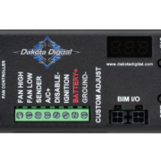
Dakota Digital PAC-2800BT Cooling Fan Controller
This blog post is going to show you how to use the Dakota Digital PAC-2800BT to control your cooling fan with the Infinitybox system. The PAC-2800BT is a powerful controller that lets you program the temperatures that turn on and turn off your cooling fans. You have the flexibility to use any temperature sender, take in OBDII data from a modern ECU, even interface with the VHX & RTX gauges. We’ve blogged before about wiring the VHX and RTX gauges with the Infinitybox system. Click on the links to learn more.
There are multiple advantages to using the Infinitybox system with the Dakota Digital PAC-2800BT controller. First, you can eliminate the external relay and the fuse. These are built into the POWERCELL. Next, you can streamline your wiring. The PAC-2800BT would be located behind your dash, near the MASTERCELL. The power for the fans comes from the front POWERCELL, which is located strategically where you need it in the car. Lastly, the POWERCELL has the ability to soft-start the cooling fan. This decreases the in-rush current to the fan and lets you drive a larger fan with a smaller gauge of wire. You can read more about this at this link.
As always, we strongly encourage you to read and understand the manuals for anything that you are installing in your car. Dakota Digital has a very detailed manual for the PAC-2800BT. You can access it by clicking this link. Also, this blog post is going to cover the wiring between the Infinitybox system and the PAC-2800BT. This includes ignition power, the cooling fan triggers to the MASTERCELL and the cooling fan output from the POWERCELL. Follow the Dakota Digital instructions for wiring battery power, ground, the temperature sender and the other optional features of the PAC-2800BT.
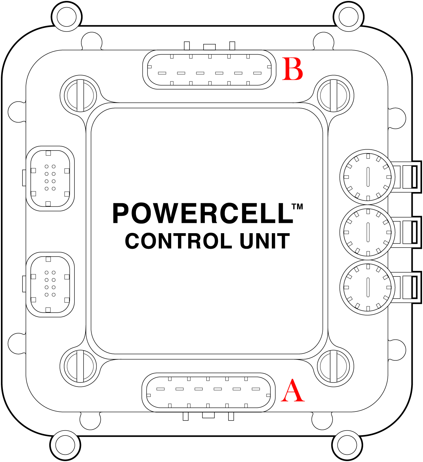
The following picture shows the connections between the Infinitybox MASTERCELL and the POWERCELL for the PAC-2800BT.
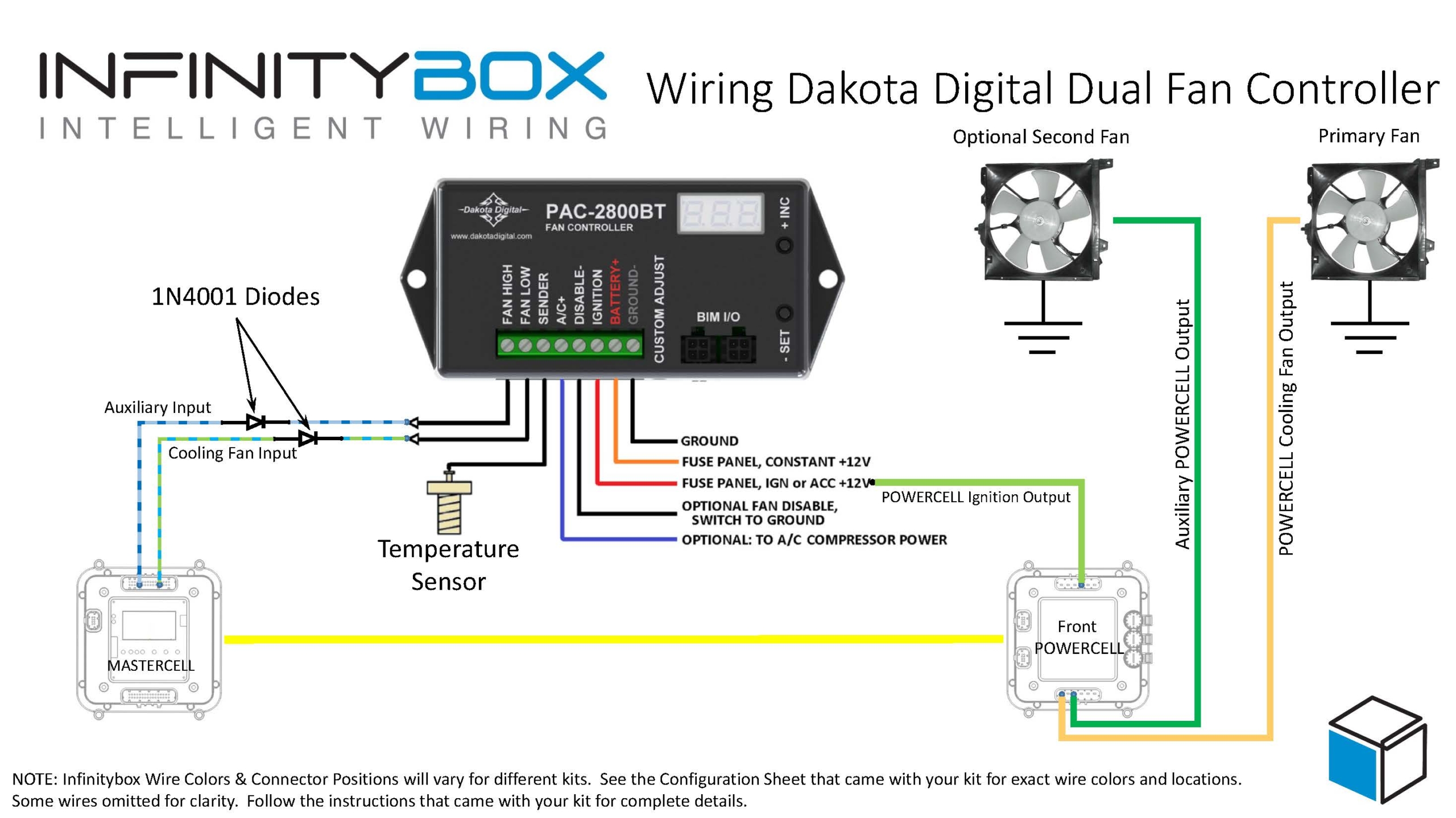
Picture of a wiring diagram showing how to wire the Dakota Digital PAC-2800 BT with the Infinitybox 20-Circuit Kit
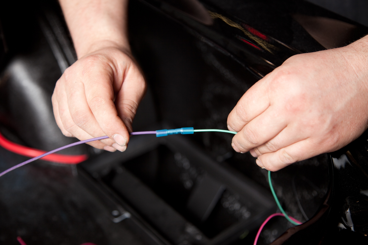
First, you need to get ignition or key-on power to the PAC-2800BT. This is going to come from the POWERCELL output for the ignition. This is output 3, the light-green wire on the front POWERCELL in most systems, . Please check your specific configuration sheet to confirm. You can going to bring this ignition power to the IGNITION terminal on the PAC-2800BT module. You are going to tap off your POWERCELL ignition output to get this power. You can splice into this wire or you can use our Splice Saver kit to create an ignition junction point.
Next, you are going to connect your MASTERCELL cooling fan inputs to the triggers on the PAC-2800BT. In most systems, your cooling fan is input 10, which is the blue wire with the green tracer. Check your configuration sheet to confirm. If you are using only one cooling fan, Dakota Digital tells you to use the FAN LOW terminal on the PAC-2800BT. We strongly recommend that you install a diode in-line between the MASTERCELL and the PAC-2800BT. This should be a 1N4001 diode that can be purchased easily from Amazon. The orientation of this diode is critical and the system will not work correctly if it is wired backwards. The diode lead on the side with the stripe should be connected to the PAC-2800BT.
Lastly, you are going to connect your POWERCELL output for the cooling fan to the wires on the fan motor. The other wire on the fan motor should be connected to a good chassis ground. This link will get you more details on wiring the cooling fan with the POWERCELL output.
The PAC-2800BT gives you the option to control two separate cooling fans. If you want to use a second cooling fan, you would simply repeat wiring an unused MASTERCELL input to the PAC-2800BT and an OPEN POWERCELL output to your second cooling fan. In most of our kits, output 8 on the front POWERCELL can be used as an auxiliary output. You can use this one to power your second cooling fan. See your specific configuration sheet for more details.
Here is how all of this works. The PAC-2800BT takes in the temperature data from the temperature sender, the Dakota Digital gauge controller or the ECU via OBDII. If the temperature it reads goes higher than the value that you programmed in it, it grounds the MASTERCELL input for the cooling fan. This turns on the cooling fan input. The MASTERCELL sends a command to the POWERCELL in the front of the car to turn on the output for the cooling fan. When the temperature drops below the set point that you programmed in the PAC-2800BT, it turns off the MASTERCELL input for the cooling fan. The MASTERCELL sends a command to the front POWERCELL to turn off the fan. It is that easy.
If you choose the option to use two cooling fans, the PAC-2800BT will manage both fans together to control the engine temperature.
There is a PDF copy of this wiring diagram available on our website. Click this link to download it.
Give our team a call at (847) 232-1991 if you have any questions about wiring the Dakota Digital PAC-2800BT with our Infinitybox system. You can also contact our team directly by clicking this link.
 Copyright Infinitybox, LLC 2021. All Rights Reserved.

 Copyright Infinitybox, LLC 2021. All Rights Reserved.
  Copyright Infinitybox, LLC 2021. All Rights Reserved.