Back-Up Lights
The back-up lights are the next thing to wire in our customer’s 1967 Mustang project. We’re getting to the end of the switches that we need to wire to the MASTERCELL.
If you look at your configuration sheet, you will not see a dedicated output for back-up lights. Depending on the vintage of the car and the manufacturer, there may or may not be back-up lights on the car. We don’t dedicate an output to this but you can use any of the OPEN outputs on your rear POWERCELL.
This link will take you to the configuration sheet for the system that we are installing in this 1967 Mustang. This link will take you to our previous post in this series going through the details of the configuration sheet. You will see that there are several outputs that are labeled as OPEN on the configuration sheet. Depending on the version, you may have 4 to 6 OPEN outputs. OPEN means that there is no specific function assigned to the output. These can be used as generic outputs. You will note that the personality for these outputs is TRACK. That means that the output will track the switch. When the switch is on, the output is on. When the switch is off, the output is off. You can use OPEN outputs for things like amp triggers, extra lights, transmission cooler fans, secondary fuel pumps and back-up lights.
Output 5 on the rear POWERCELL is OPEN. This is the white wire coming from the B harness. The MASTERCELL input is the white wire with the red wire. This is input 2 on the MASTERCELL A input harness.
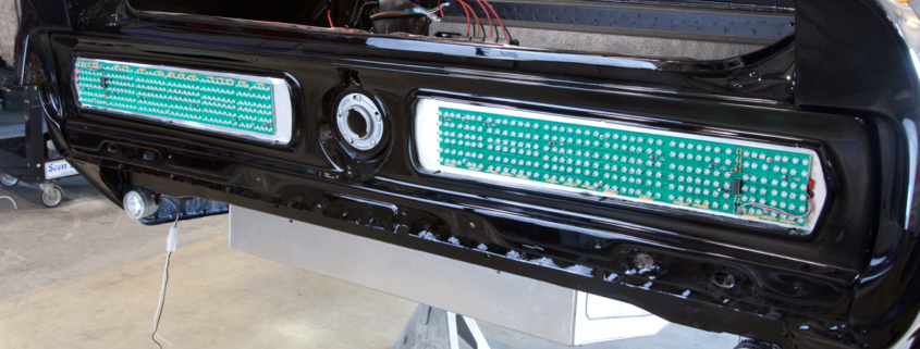
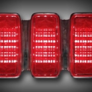
We previously connected the white wire from the rear POWERCELL to the back-up lights in the rear of the car. The customer is using the tail light assembly from Mustang Projects. You can read about that in this blog post. The white wire connects to the tail light assembly. Then the assembly needs to get connected to ground. Follow the instructions that came with your back-up lights for the exact wire colors.
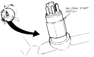
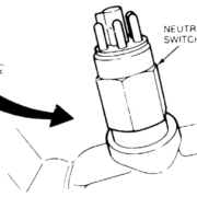
Next, the MASTERCELL input wire needs to connect to a switch that closes when the transmission is in the reverse position. Our customer is using a Ford AOD transmission in this car. There is a dedicated connector on the driver’s side of the transmission. We connected to this connector in a previous post for the neutral-safety signal. We are going to connect to the same connector for the reverse signal.
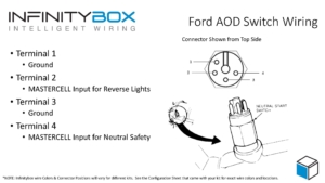
This diagram will show you which terminals on the Ford AOD transmission you need to connect to ground and to the MASTERCELL input harness.
Terminal 1 on the transmission connector needs to get connected to ground. Terminal 2 needs to connect to the MASTERCELL input for the back-up lights. In our case, this is the white wire with the red tracer on the MASTERCELL A input harness. This link will take you to a PDF of this document.
When the transmission is in the reverse position, the switch makes a connection between terminals 1 and 2. This connects the MASTERCELL input to ground. When the MASTERCELL sees the input connect to ground, it sends a signal to the POWERCELL in the rear of the car to turn on the output that we have chosen for the back-up lights. When the transmission is taken out of reverse, the switch opens which disconnects the MASTERCELL input from ground. The MASTERCELL sees this change and sends a command to the POWERCELL to turn off the output that we have chosen for the back-up lights.
Most transmissions will have a set of contacts for a reverse switch. In other cases, there will be a switch in the shifter that will be made when the transmission is in the reverse position. Check the literature that came with your transmission or your shifter.
That’s it. Having a POWERCELL in the rear of the car makes wiring the back-up lights very easy. There is no extra wire to run to the back of the car. You are already using the existing POWERCELL to manage this.
Please contact our team with any questions about wiring with our Infinitybox system. You can contact a member of our technical support team by clicking this link.

 Copyright Infinitybox, LLC 2021. All Rights Reserved.
 Copyright Infinitybox, LLC 2021. All Rights Reserved.


Leave a Reply
Want to join the discussion?Feel free to contribute!