Over the next few videos, we’re going to continue our theme on good planning. Specifically, we’re going to talk about picking the best locations for the major components that come with your Infinitybox system. We’re installing our 20-Circuit Kit with inLINK and inRESERVE in our 1979 CJ7. To get the most out of our install, we want to pick the best locations for the MASTERCELL, the front & rear POWERCELLs, the MEGA fuse holder and the inRESERVE solenoid. We’ve broken this up into 5 different videos, talking about what you need to consider for each part. This video covers picking the best location for your MASTERCELL.
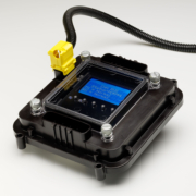
The Infinitybox MASTERCELL
The MASTERCELL is the brain of your 20-Circuit Kit. It connects to all of your switches. These include your ignition switch, turn signal stalk, brake pedal switch, headlight switch, fuel pump & cooling fan trigger and any other accessory switches that you may have in your car or truck. The MASTERCELL sends commands to the POWERCELLs when you turn a switch on or off. You can learn more about the MASTERCELL and what it does by clicking this link.
There are two important things to consider when you’re picking the location for your MASTERCELL. First, you want the MASTERCELL as close to your switches as possible. This keeps the wiring short and makes it easy to install. Second, you want to have easy access to the MASTERCELL for troubleshooting and diagnostics. There are tons of diagnostic features built into the MASTERCELL. You can learn about them at this link. To access these features, you need to be able to get to the MASTERCELL, remove the protective cover, press the buttons and read the inSIGHT LCD screen.
In our 1979 Jeep CJ7, we’re going to mount the MASTERCELL in the glove compartment. There is a convenient open pocket behind the door for the glove compartment. This puts the MASTERCELL close to all of the switches on the dash. That will make the dash wiring short and efficient. With the door open, we can easily take off the MASTERCELL cover, press the buttons and read the inSIGHT screen. When we close the door, the MASTERCELL disappears.
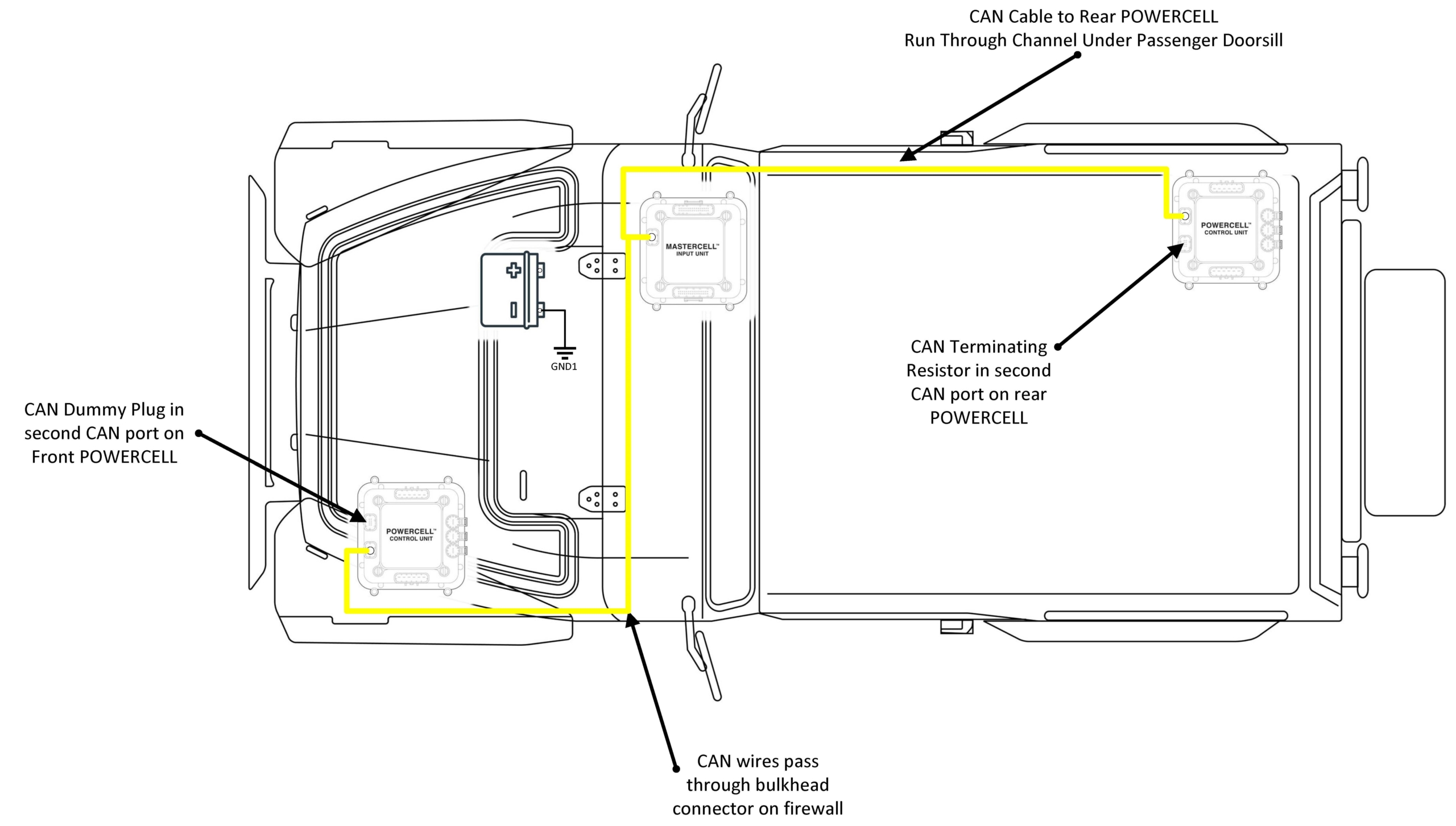
This picture will show the location of the MASTERCELL and POWERCELLs in the Jeep and how we routed the CAN cable between the cells.
Infinitybox Jeep CJ7 Wiring Diagram- CAN Cable Routing
Picking the best location for your MASTERCELL will make your switch wiring simple and efficient. It will also make troubleshooting and diagnostics easier if you need them. Keep watching for more in our 1979 Jeep CJ7 Install Series.
Our Infinitybox system has powerful diagnostic and troubleshooting features built into it. The MASTERCELL in your 20-Circuit Kit includes our inSIGHT LCD Screen. This screen is your window into the Infinitybox system and it gives you access to the MASTERCELL Input Troubleshooting and Diagnostics. By pressing a few buttons on the MASTERCELL, you can put it into its Messaging Mode. This blog post and the attached video will show you how the Messaging Mode can help you wire your car faster and identify problems easily.
All of your switches connect to the MASTERCELL. These include your ignition and starter switches, your turn signal switches, your brake pedal switch, the switches for your lighting, your fuel pump and cooling fan triggers and any other switches that you have for your accessories. The MASTERCELL continuously watches the state of your switches. If it sees one of these inputs turn on or off, it sends commands to the POWERCELLs or inMOTION cells in your system and commands them to turn an output on or off.
The MASTERCELL can be put into its Messaging Mode. This mode opens up the MASTERCELL Input Troubleshooting and Diagnostics feature in your Infinitybox 20-Circuit Kit. To put the MASTERCELL into Messaging Mode, you simply press and hold the “SCROLL UP” and “SELECT” buttons under the clear cover. These are the two buttons on the right, under the inSIGHT LCD screen. Press these buttons together, hold them for one second then let them go. You will get a message on the screen that says “inSIGHT WILL DISPLAY ALL INPUT CHANGES FROM ANY SOURCE”. You will also note that the back light of the inSIGHT LCD will turn on and stay on.
When you turn any MASTERCELL on or off, the inSIGHT screen will confirm that. It will tell you which input the MASTERCELL say turn on or off. It will also tell you which cell it is supposed to be controlling and which output.
The following video goes through this in detail. You can see which buttons to press to put the MASTERCELL into Messaging Mode. You will also see what the messages on the MASTERCELL screen look like when you turn inputs on and off. Check out the video here.
Messaging Mode is a very powerful tool. You can use it as you go through the process of wiring your car or truck with our Infinitybox system. You can wire each switch, step by step, then use Messaging Mode to confirm that you have the correct input wired to the switch by following the details of your Configuration Sheet. You can also use this to confirm that you switch is working correctly and that you have good grounds for each of your switches.
If you have problems on the road, you can easily put the MASTERCELL into its Messaging Mode and check for any issues with your switches or the wiring from the MASTERCELL. No tools are needed.
If you have any additional questions about the MASTERCELL Input Troubleshooting and Diagnostics features of the Infinitybox system, click here to contact our team.
https://www.infinitybox.com/wp-content/uploads/2021/02/Infinitybox-Video-MASTERCELL-Messaging.png7201280adminhttps://www.infinitybox.com/wp-content/uploads/2021/02/infinitybox-logo-https-1-1.pngadmin2020-03-25 08:09:572021-02-26 08:13:41MASTERCELL Input Troubleshooting and Diagnostics
It is time to get into the next phase of wiring this 1967 Mustang with our Infinitybox 20-Circuit Kit. We got the cells mounted, mounted the Mega fuses, wired primary power from the battery, ran the CAN cable and wired the outputs to the POWERCELLs. It’s time to start wiring switches to the MASTERCELL inputs.
Here’s a quick refresher. Our Infinitybox system is different than any other wiring harness on the market. Instead of having one central box full of fuses and relays with wire running everywhere in the car, our system is broken into smaller modules. Our POWERCELLs are mounted in the front and rear of the car. They contain the fuses and relays to turn your accessories on and off. The MASTERCELL connects to the switches. You mount the MASTERCELL under the dash and wire your switches to it. The MASTERCELL sends commands to the remote POWERCELLs through our CAN cable to control your lights, fans, fuel pump, horns, ignition, starter solenoids and other switched functions. This is going to be the first in a series of posts talking about wiring switches.
Remember that all of your switches will connect to your MASTERCELL. This includes switches for your ignition, starter, turn signals, brake lights, headlights, parking lights, high-beams, cooling fans, fuel pump, horn and anything else that you need to turn on and off in the car. There is no direct connection between your switch and the output. The MASTERCELL watches all of the switches. When it sees a switch turn on or off, it sends a packet of data through the CAN cable to the remote cells in the car. These cells could be POWERCELLs or inMOTION cells. The remote output cells are what control the current flowing to your switched loads.
The MASTERCELL needs a simple trigger signal from each switch. These triggers are a connection to ground. Each trigger takes a very small amount of current to send the signal to the MASTERCELL, less than 0.001-Amp. This picture shows a very simple switch wired to a MASTERCELL input.
Simple diagram showing how to wire a switch to the Infinitybox MASTERCELL
In this diagram, the MASTERCELL input wire connects to one terminal of the switch. The other side of the terminal needs to connect to ground. When the switch is on (closed) there is a path through the switch to ground. This is what triggers the input on the MASTERCELL. This picture shows using one of the ground wires that is included in the MASTERCELL input harness.
There are lots of advantages to using this kind of input when you are wiring a car. Ground switching the inputs means that you do not need to run a positive wire to each switch. The MASTERCELL input harnesses have ground wires that you can use for your switches. You can also use the chassis in the car as the ground reference for your switches. You just need a good metal-to-metal connection to ground.
Another advantage is that it takes a very small amount of current to turn on an input. This means that we can use a much smaller gauge of wire in the input harness. We use 22-AWG TXL wire on the inputs. This will reduce the bulk of harness behind your dash. It also means that there is no high-current behind your dash. All of the high-current control is at the POWERCELL. It is always the small signal current through the MASTERCELL input wire regardless of what is being switched at the POWERCELL. This means that you can use practically any switch to turn things on and off in your car. You can use the original switches that came with the car. You can use any aftermarket switch. There is very little current flowing through the switch.
Just a quick warning: The MASTERCELL inputs are designed to be switched to ground. You must not wire your switches so that battery voltage can be applied to a MASTERCELL input. Doing this may damage the circuitry inside the MASTERCELL and this will void the warranty. Contact us with questions if you are uncertain about how to properly connect something to a MASTERCELL input.
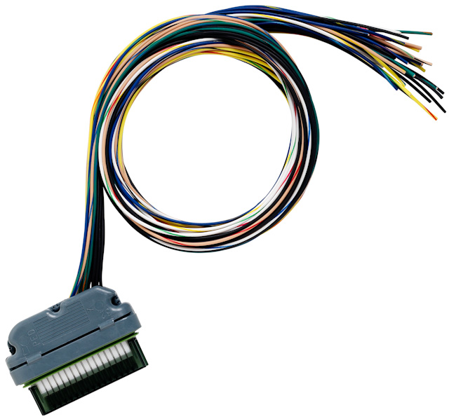
Every kit comes with a MASTERCELL A input harness. This picture shows this harness.
MASTERCELL A Input Harness
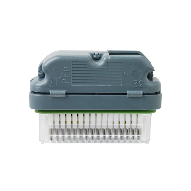
All of your switches will connect to the wires on this harness. The B connector socket at the bottom of the MASTERCELL must have the input dummy plug installed to keep the cell sealed. This picture shows the MASTERCELL input dummy plug.
Sealing plug for MASTERCELL B Port
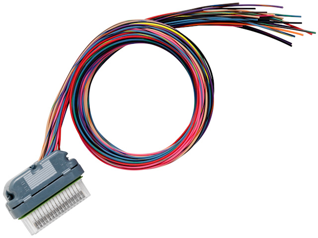
If you have a third POWERCELL as part of your system or if you have added inMOTION to your kit, you will get the MASTERCELL B harness. This picture shows this harness.
MASTERCELL B Input Harness
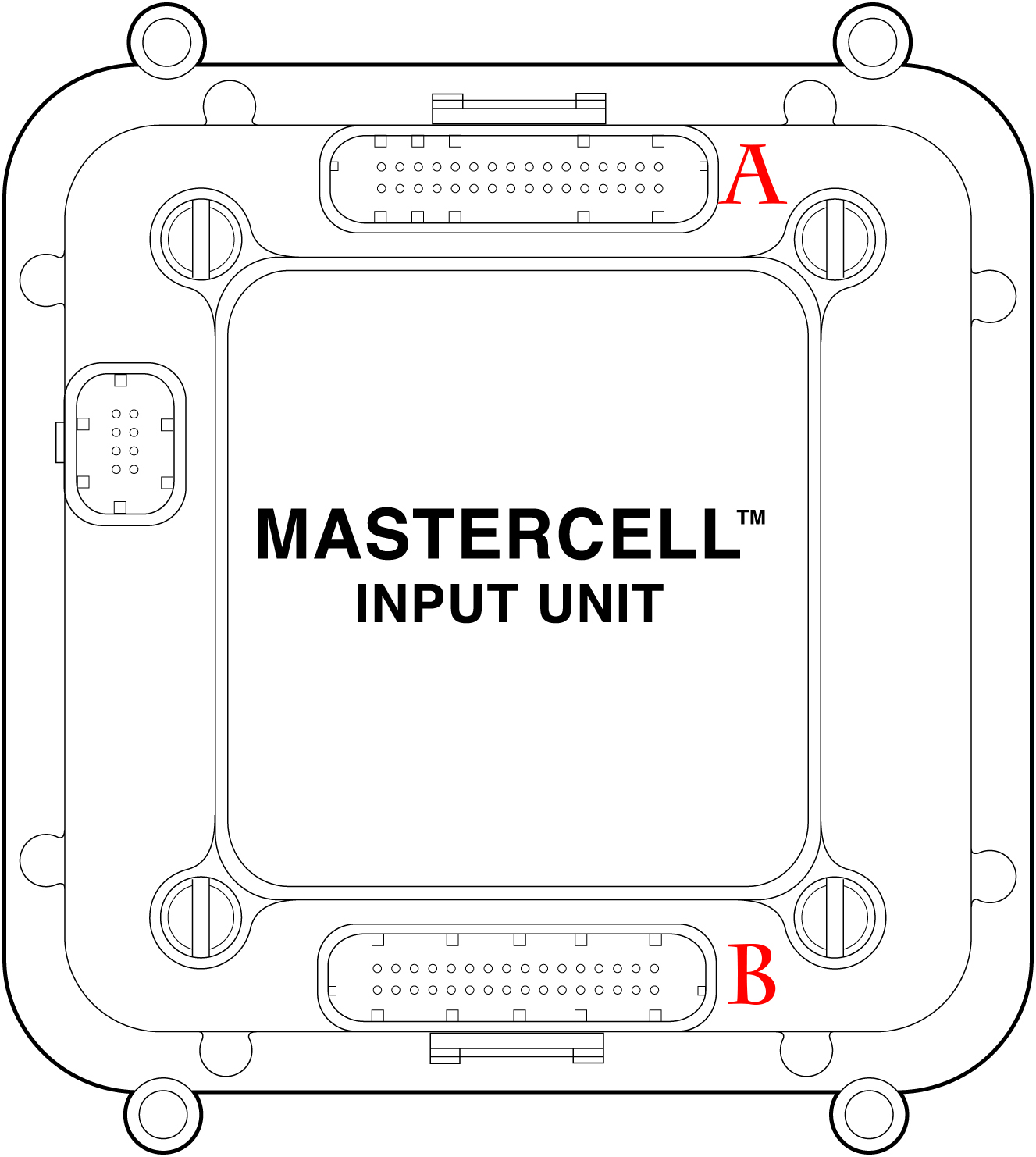
Your configuration sheet will show which harnesses have the inputs for your different switches. This picture shows which is the A & B input connector socket on your MASTERCELL.
Illustration of Infinitybox MASTERCELL labeling output connectors
In the case of this 1967 Mustang project, the MASTERCELL is mounted under the dash, to the left of the pedals. The input wires will run from the MASTERCELL to all of the switches. This is a great location for this because all of the wire runs will be short.
The Configuration Sheet is your road map to wiring the car with the Infinitybox 20-Circuit Kit. It it included in the box and tells you the wire colors that connect to your switches and to your switched outputs. This is a really important document so let’s spend a few minutes reviewing it.
All of the MASTERCELL input wires and POWERCELL output wires are color coded. The same is true for the inMOTION output harnesses. You are going to use the Configuration Sheet to pair these input and output wires to their switches and the outputs.
Depending on the kit that you ordered and the accessories that you have, your configuration sheet is going to be unique to your system. Likewise, you’ll have a configuration sheet that is specific to you if we did custom programming for your system. We also have different configuration sheets for where the engine is located in the car. The Front-Engine configuration is our most common and is probably the most self-explanatory. This is used for cars where the engine is in the front of the car. The outputs for the ignition and starter are on the front POWERCELL.
If you are building a mid-engine or rear-engine car, you’d use the Rear-Engine configuration. The outputs for the ignition and starter are on the rear POWERCELL.
We also have specific configurations for component cars made by Factory Five. These include kits specifically configured for the Hot Rod, the GTM and the 818. These are based on things that we have learned from hundreds of systems that we sold into guys building these cars. If you’re building the MK4 Roadster or the Type 65 Coupe, you’d use the standard Front-Engine configuration.
Let’s take a look at an example. This picture from a configuration sheet showing the details for the Headlights. Click on this image to blow it up to see the detail.
Example of headlight wiring details from the Infinitybox configuration sheet
The first column is Function. This describes what is being controlled. You’ll see that there are rows for your ignition, starter solenoid, head lights, parking lights, high-beams, horn, cooling fan, turn signals, 4-ways and brake lights. There are also rows that marked as OPEN. These are generic and can be used for any other accessory that you have in your car.
The next column is Switch Input. This is the number that we use to identify the MASTERCELL inputs. There are 48 inputs on a MASTERCELL. Please note that the input number does not line up with the cavity marking on the input connectors. Click on this link to get a document that connects the MASTERCELL input number to the cavity marking on the connector. The MASTERCELL input wires are going to connect to the switches in your car. We’ll talk about that in a later post.
The next column is MASTERCELL Connector. There are two input connectors for a MASTERCELL, each has 24 inputs. The majority of your inputs will be on the A connector which plugs in the socket above the MASTERCELL screen. For systems with accessories like inMOTION and additional POWERCELLs, you will be using the B connector which is located below the MASTERCELL screen. Some kits do not come with this MASTERCELL B harness.
The next column is POWERCELL Address. This tells you which POWERCELL has the output that will turn on with that input. In the case of our headlight example, the POWERCELL address is 1. This means that the headlight output is on the front POWERCELL. You will see that there are some rows with POWERCELL address that say 1:2. This means that outputs on both POWERCELL 1 and POWERCELL 2 will turn on with this input. Examples include parking lights, turn signals and 4-ways. This link will show you how to set your POWERCELL addresses.
The next column is POWERCELL Connector. Just like the MASTERCELL, there is an A & B output connector on the POWERCELLs. In the case of our headlight example, the headlight output is on the B POWERCELL connector. Your manual will show you which output harness plugs into which socket on the POWERCELL.
Next you get the Personality column. This describes how the output will act when the input is turned on. This separate blog post will get you more information on output personalities. Click here to see it. In the case of the headlight example, the output will track the input and it will soft-start.
Next you get the POWERCELL Output column. This describes the number of the output on the POWERCELL that is turned on with the input on that row. For our headlights, that is output number 5.
The last two columns are the most important and most practical. Ignoring everything to the left, these two columns tell you the MASTERCELL input wire color and the POWERCELL output wire color. For the headlights, you are going to connect the White wire with the Green tracer to the headlight switch. You are going then take the White wire from the POWERCELL and connect that to your headlights. When you turn on the headlight switch, the White-Green wire will get grounded by the switch. The MASTERCELL sees this input turn. It sends a command to the POWERCELL to turn on the headlight output. This is the white wire.
This is one of the areas where our Infinitybox system is dramatically different from a traditional wiring harness. Your switches connect to the MASTERCELL. Your lights, fans, pumps, ECU’s, starter solenoid and other outputs connect to the POWERCELL.
There is a video on our YouTube channel that goes through the configuration sheet in more detail. You can catch this video below.
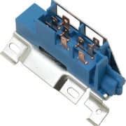
Wiring any switch into the Infinitybox system is really easy. You just have to remember that the MASTERCELL input wire needs to get connected to ground to turn something on. In most cases, you can simply connect the MASTERCELL input to one side of the switch and ground the other. When you close the switch, the MASTERCELL input gets connected to ground and the output turns on. This blog post is going to cover wiring the GM Ignition Switch with our Infinitybox system.
With most OEM switches and the original switches that are in your car, you can connect the battery feed from the switch to ground. Then you connect the MASTERCELL input wire to the terminal on the switch that powered the original function. Here’s a good example for a GM Ignition Switch. This GM Ignition Switch was used in most Chevrolet and Pontiac cars from 1969 through 1994.
Picture of a wiring diagram showing how to connect Infinitybox MASTERCELL inputs to the GM Ignition Switch
You connect the original battery feeds for the GM ignition switch to ground. You then connect the MASTERCELL input wires for the ignition and starter to their respective terminals on the switch. When you turn the key to the ignition position, the switch connects the MASTERCELL input wire for the ignition to the ground through the battery terminal. This sends a signal to the POWERCELL to turn on the ignition output. The same thing happens when you turn the key to the starter position. We created a simple wiring diagram showing you how to wire this GM ignition switch.
For all of those guys building a Factory Five GTM with the C5 Corvette steering column, here is how you connect the Infinitybox MASTERCELL inputs to the column harness.
Connect these pins to the MASTERCELL inputs:
Pins D, Z, X & W – Connect to Ground
Pin V – Horn input to MC
Pin R – Park lights input to MC
Pin L – Low Beam input to MC
Pin K – High Beam Input to MC
Pin G – Left Turn Input to MC
Pin F – Right Turn Input to MC
Depending on which turn-signal style you want (1-filament vs. multi-filament), refer to your configuration sheet for the specific wire colors. You can download the Infinitybox GTM Configuration Sheet by clicking here.
https://www.infinitybox.com/wp-content/uploads/2021/02/MASTERCELL.jpg17601800adminhttps://www.infinitybox.com/wp-content/uploads/2021/02/infinitybox-logo-https-1-1.pngadmin2015-05-14 11:45:062021-08-23 13:46:28Wiring MASTERCELL Inputs to the GTM Column
 Copyright Infinitybox, LLC 2021. All Rights Reserved.
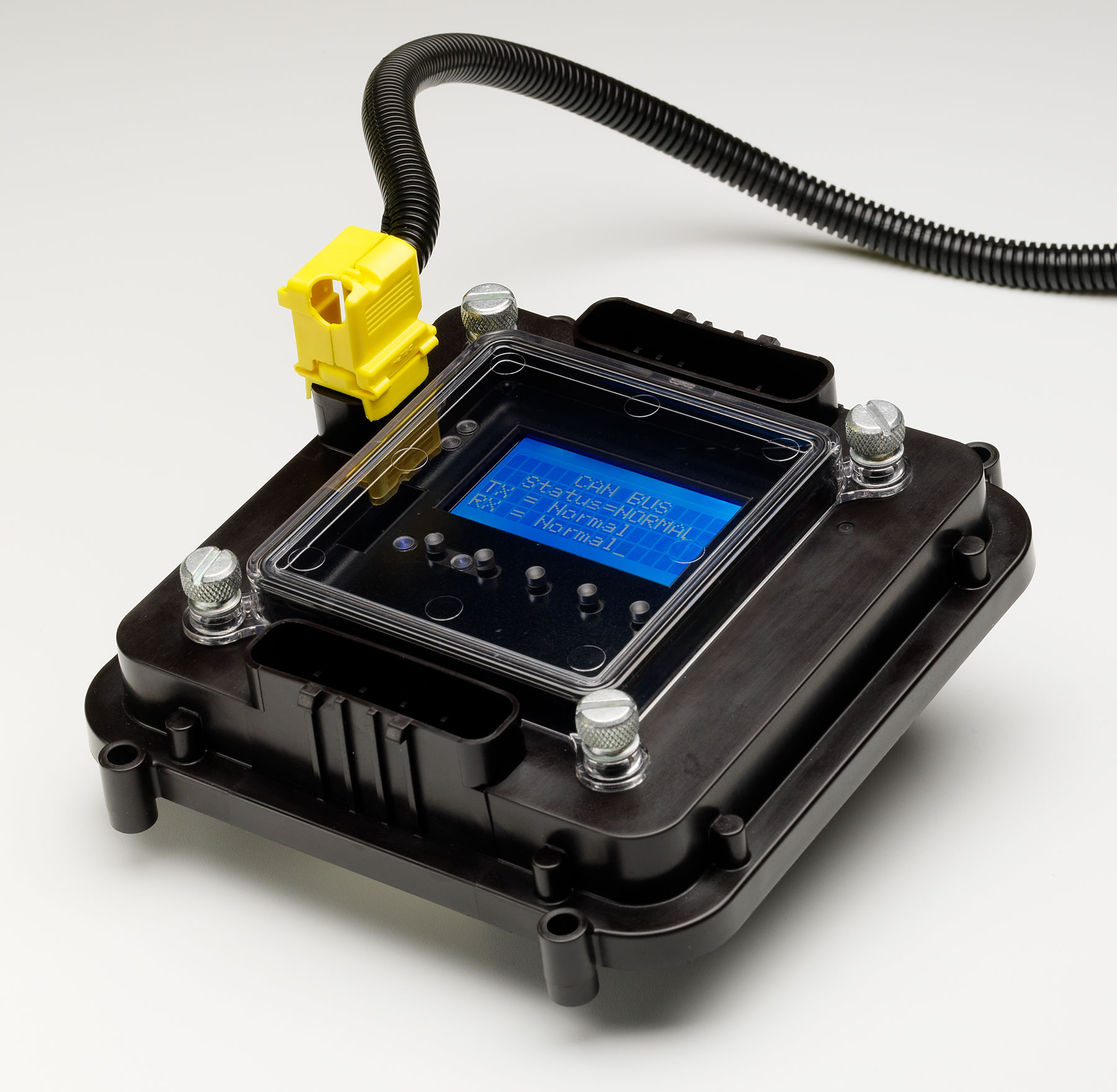
 Copyright Infinitybox, LLC 2021. All Rights Reserved.
 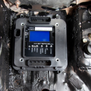 Copyright Infinitybox, LLC 2021. All Rights Reserved.
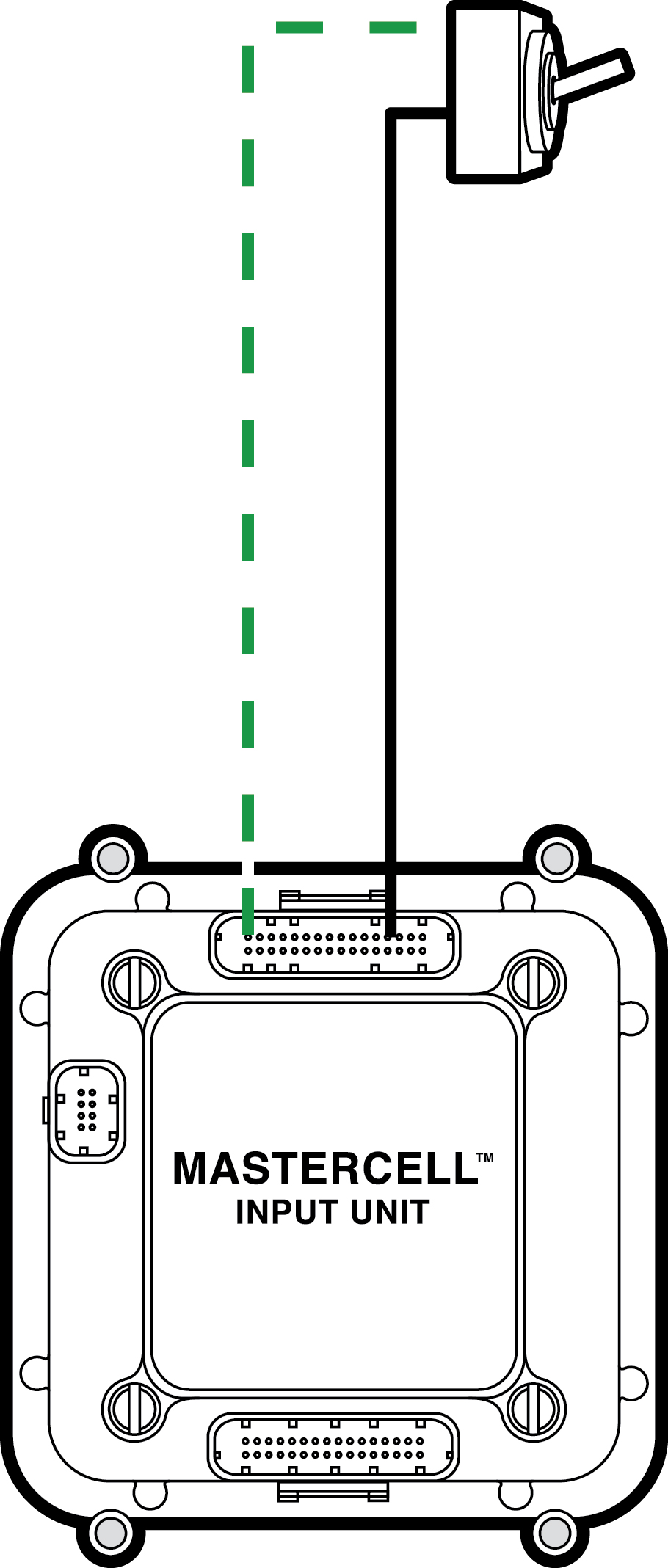
 Copyright Infinitybox, LLC 2021. All Rights Reserved.
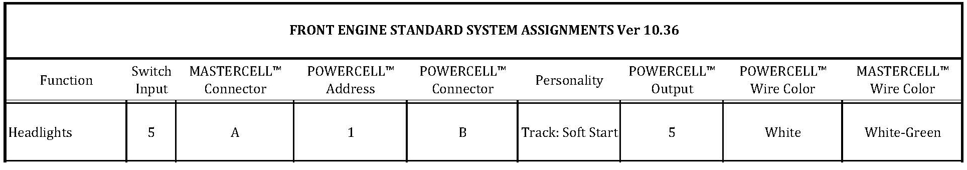

 The Infinitybox MASTERCELL