Copyright 2022 Infinitybox, LLC. All Rights Reserved.
 Dakota Digital GSS-3000
This blog post will show you the connections that you need to make between your Infinitybox 20-Circuit Kit and the Dakota Digital GSS-3000 Universal Gear Shift Sender. The GSS-3000 is designed to drive the gear selector indicators on your dash from any automatic transmission. Their kit has a rotary potentiometer that connects to the shift linkage on the transmission. It learns the position of the different gears and sends signals to indicators on your dash to show you what gear you are in. It is a simple and clever product. The Dakota Digital GSS-3000 has contacts that are designed to drive your back up lights when you have the transmission in reverse. It also has a set of contacts for a Neutral Safety Switch. This sends out a signal when the transmission is in park or neutral and it is safe to start the engine. Your Infinitybox system can take in these two signals to easily drive your back up lights and manage your Neutral Safety Switch. Keep reading to learn more.
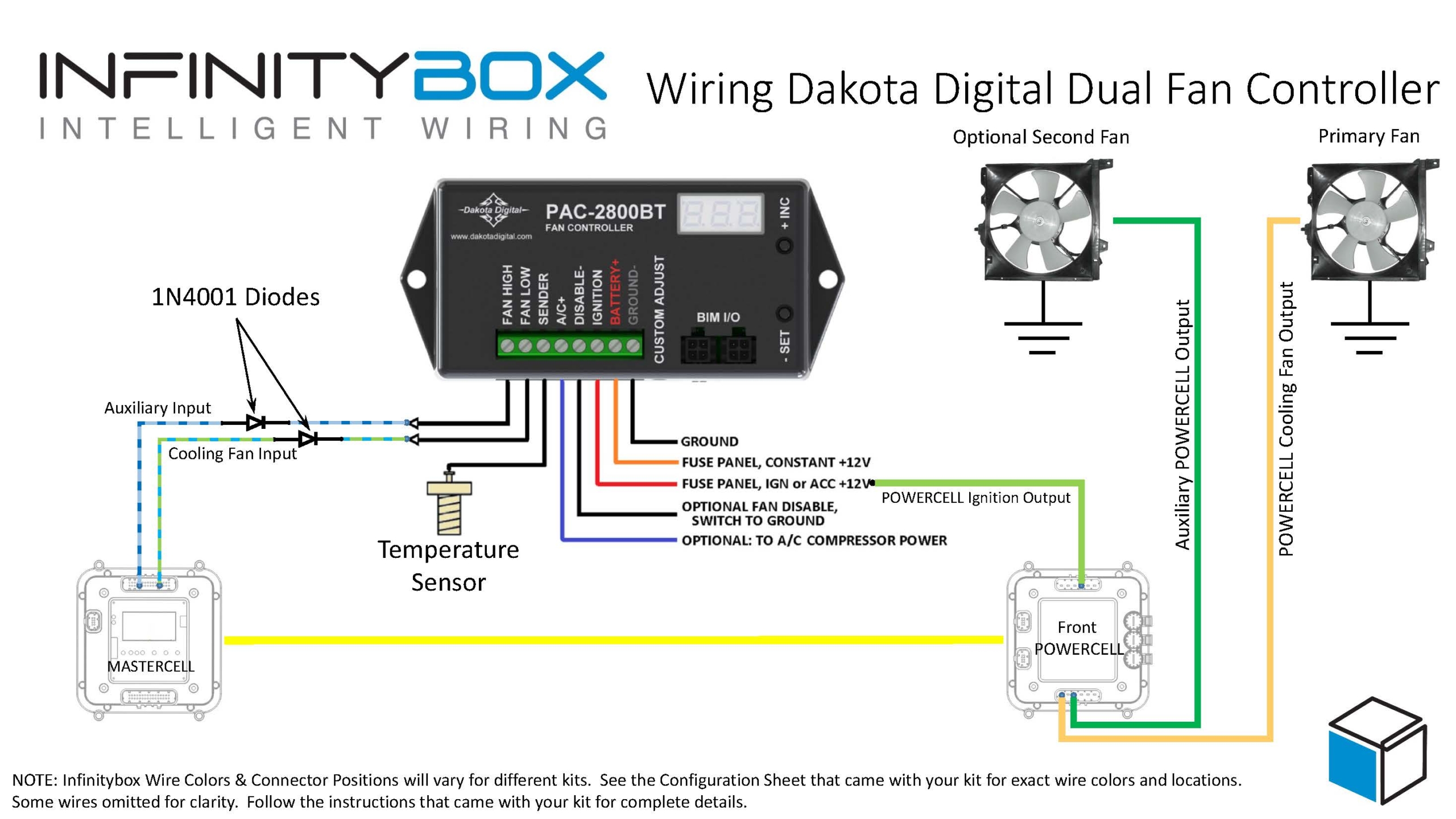
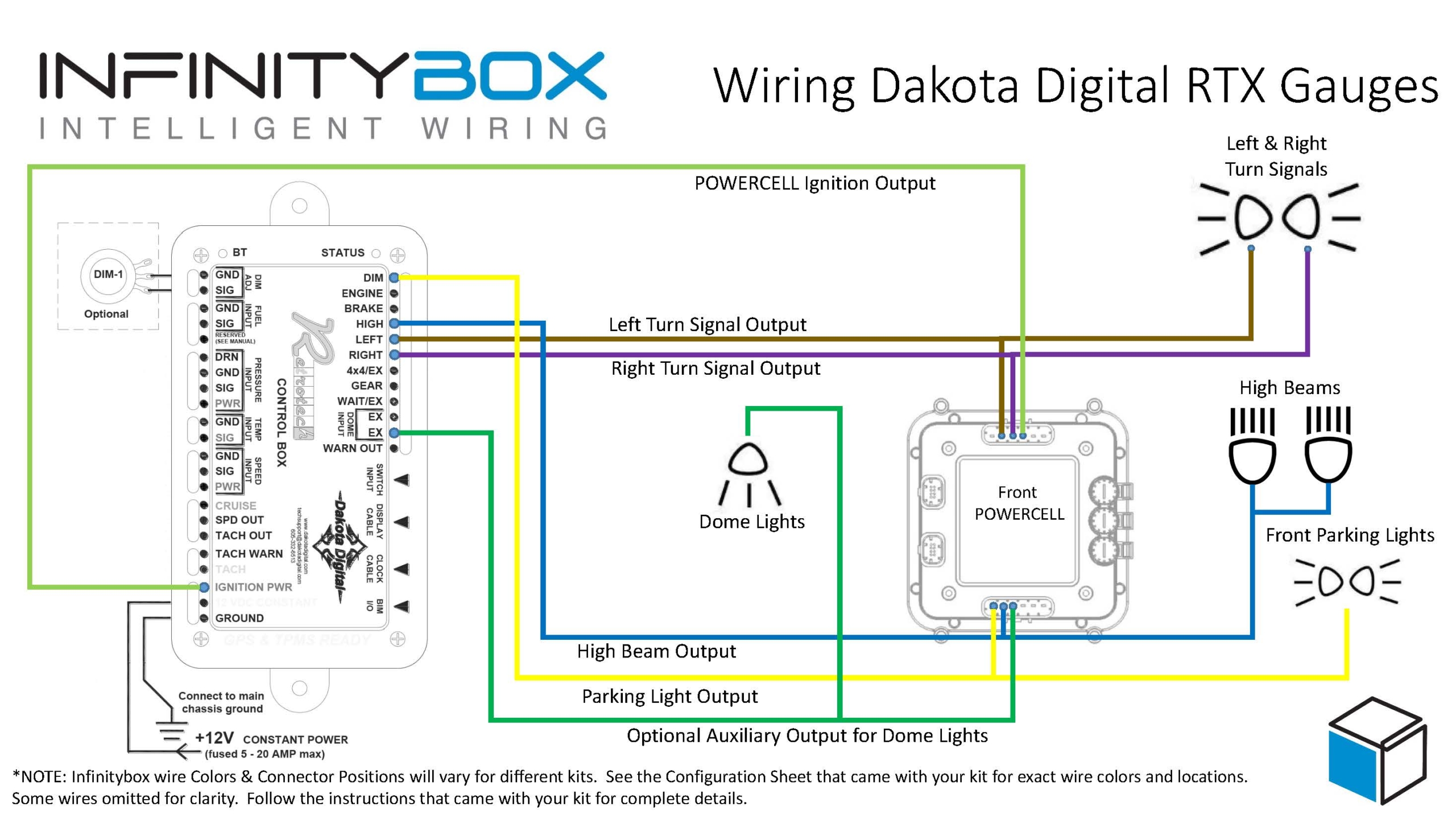
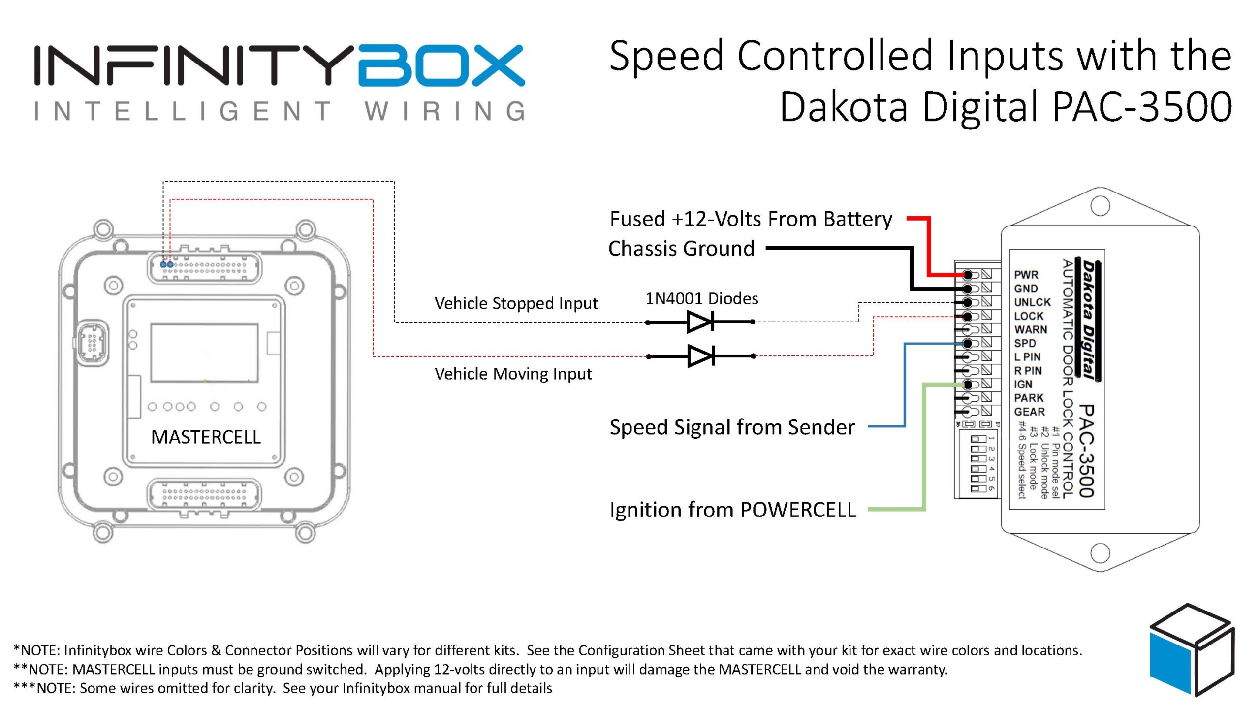
Before you go any further, it is important that you read and carefully understand the instructions for your Dakota Digital GSS-3000 Universal Gear Shift Sender. You can download these instructions from their website by clicking here. This blog post is only going to cover the ignition power to the GSS-3000, the neutral safety signal and the connection to the back up lights. Please follow their instructions for the rest of the wiring to the module. This picture will show the wiring diagram for the connections to the GSS-3000.
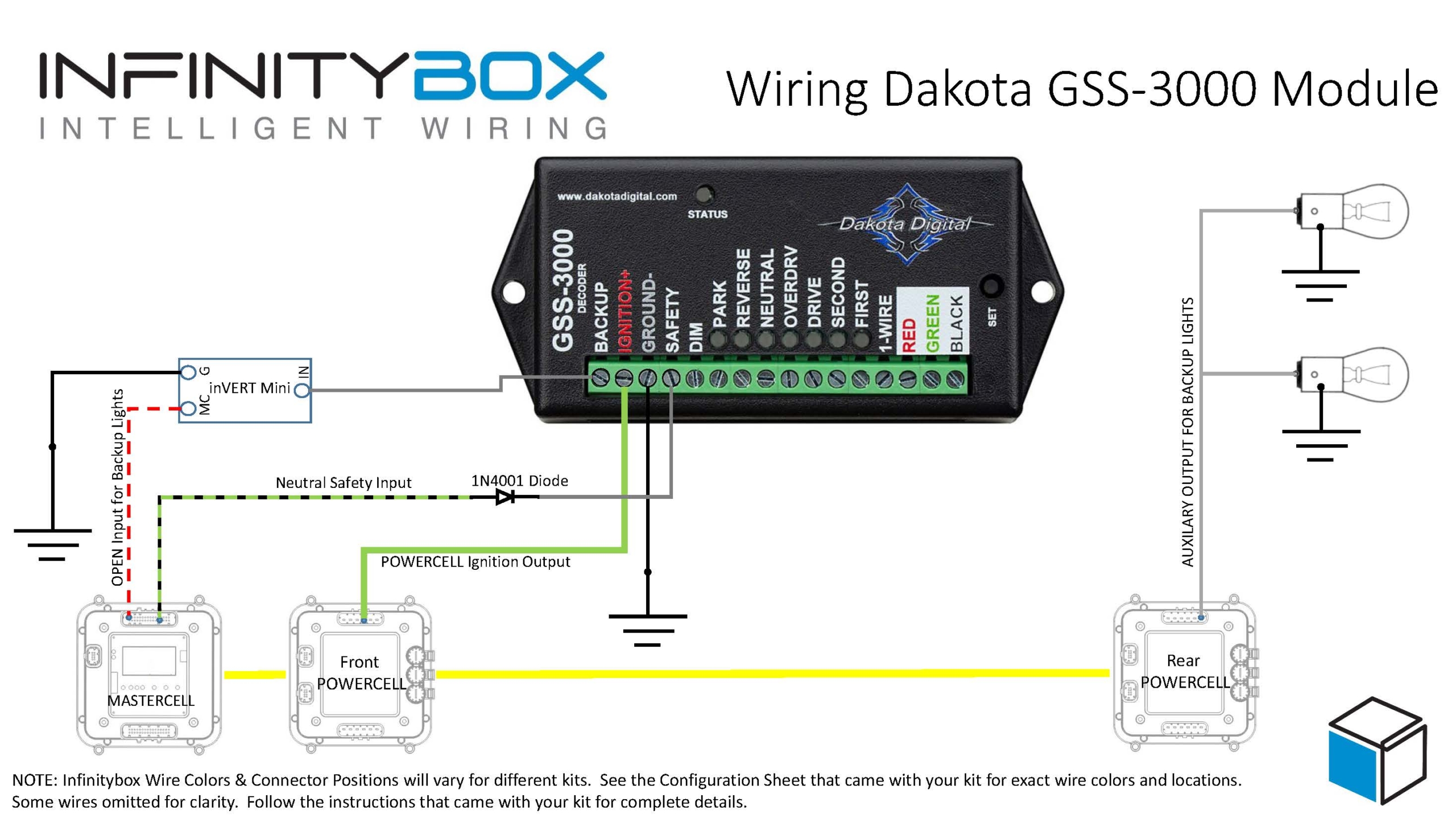
Picture of Infinitybox Wiring Diagram for the Dakota Digital GSS-3000
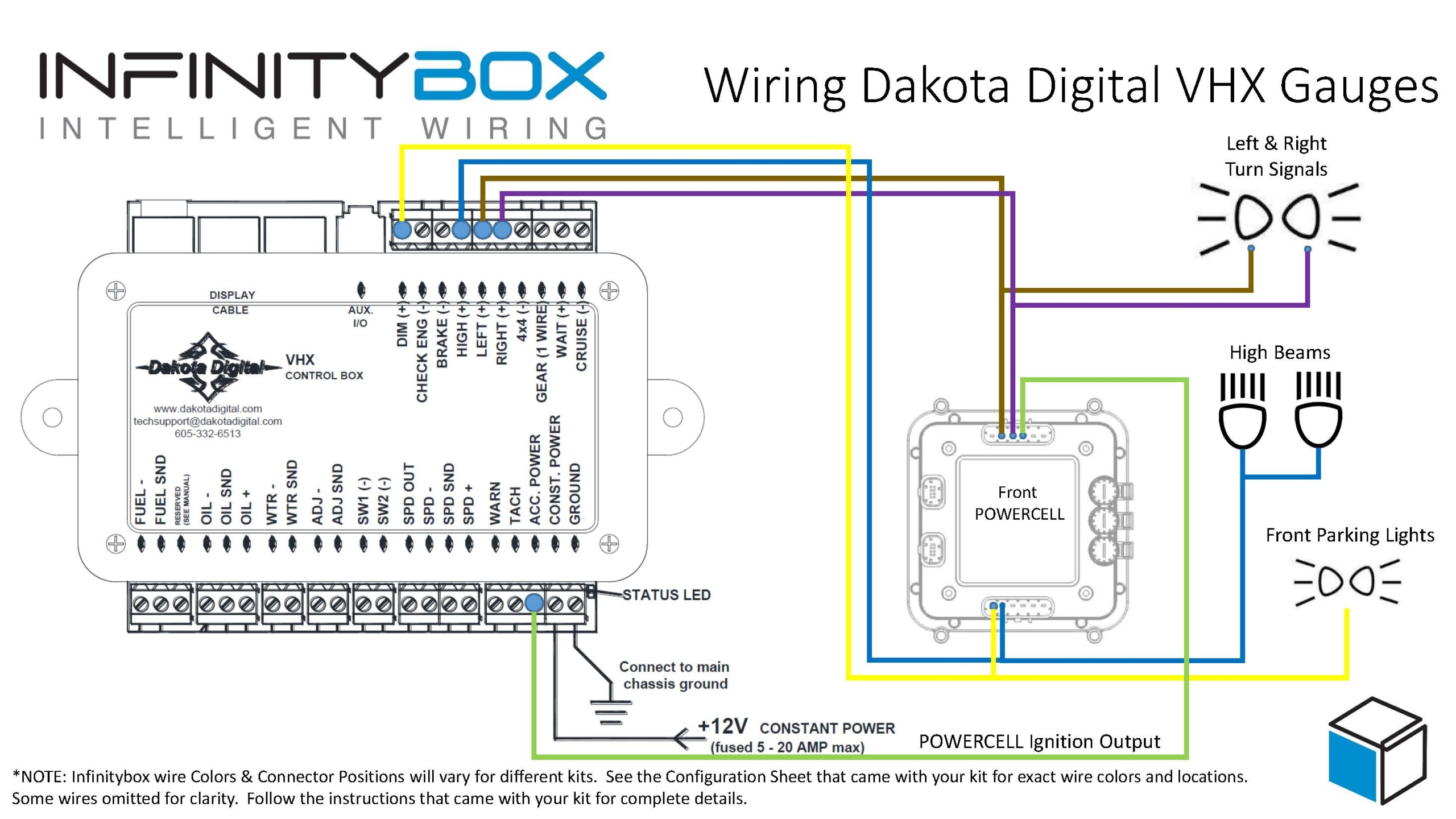
First, you need to provide key-on ignition power to the module. When the key is in the run position, the module will get its power. You’re going to tap into the ignition output on your front POWERCELL. Check your configuration sheet for the wire color for your ignition output. You can splice into this wire directly or you can use one of our Splice Saver Kits to make a simple and clean connection for ignition power.
Next, you can take their Back Up signal and use it to control the back up lights in the back of you car. The advantage of doing it this way is that you’re running less wire. The signal will come from the GSS-3000 in the front of the car and connect to the MASTERCELL, also in the front of the car. The back up lights will get their power from the rear POWERCELL. You are not running a wire all the way from the GSS-3000 in the front of the car to the back up lights in the rear of the car. The GSS-3000 puts out a positive signal for the back up lights. You need to use one of our inVERT Minis to flip this to a ground signal. See the details in the wiring diagram for how to make these connections.
Lastly, you can use the Dakota Digital GSS-3000 to send the MASTERCELL the signal for the Neutral Safety Switch. The MASTERCELL needs to see a ground signal through the input for the Neutral Safety Switch. Check your configuration sheet for specifics on the wire color for your system. This blog post will get you more details on the Neutral Safety Switch input. In a lot of transmissions, there is a switch built into them that will give you this signal for when it is safe to start the engine. If your transmission does not have a built-in safety switch, you can use the signal from the GSS-3000. This is a ground signal from their SAFETY terminal. We recommend wiring a 1N4001 diode in series with the MASTERCELL input to isolate the MASTERCELL from the GSS-3000. This blog post will get you more details about wiring this diode in line. When you have the transmission in the park or neutral position, the MATERCELL will get the signal that it safe to start the engine.
The is an important consideration here regarding using the GSS-3000 neutral safety signal and the Infinitybox built-in One-Button Start feature. This feature will not work if you are taking the neutral safety signal from the GSS-3000. Since the GSS-3000 is getting its power from the ignition output from your POWERCELL, the module will not trigger the neutral safety signal in time for the MASTERCELL to process this. You will need to use an external neutral safety switch if you want to use our One-Button Start feature and the GSS-3000.
You can download a PDF version of this wiring diagram by clicking this link.
Our technical support team is always available to help you wire your car or truck with our Infinitybox system. Click this link to contact our team with any questions.