 Copyright Infinitybox, LLC 2021. All Rights Reserved.
 MASTERCELL Error Log
Our Infinitybox system is full of tools that help you wire your car or truck faster. There are troubleshooting and diagnostic features built in that tell you simply what is going on in your car. This link will take you to our Troubleshooting and Diagnostic manual. This blog post covers the most sophisticated of the troubleshooting and diagnostic tools in the Infinitybox 20-Circuit Kit. The MASTERCELL is always watching the critical parameters for the POWERCELLs and inMOTION cells that are attached on the Infinitybox CAN network. The MASTERCELL Error Log holds any records of problems with these critical parameters and lets you easily access them for advanced troubleshooting. This may sound really complicated for a wiring system used in hot-rods and resto-mods, but this powerful tool lets our technicians help you when things aren’t working correctly.
Each of the cells in the Infinitybox system monitors their own health. Every second, they tell the MASTERCELL how they are doing and report if they’re having any problems. If there are problems, they are kept in the MASTERCELL Error Log. You can easily access the MASTERCELL Error Log by simply pressing the “HOME” and “SCROLL DOWN” buttons under the inSIGHT screen on the MASTERCELL. You press these two buttons at the same time, hold them down for one second then release them at the same time. After you do this, the MASTERCELL will display any errors that it recorded on the inSIGHT screen. The MASTERCELL can hold 8 errors in memory and displays them in order. This video will show you all of the details about the MASTERCELL Error Log.
There are three key values that are important to the Infinitybox system.
The first is battery voltage. The system needs a minimum voltage to operate safely. This is set at 7 volts. There is also a safe maximum operating voltage. That is 20 volts. If your MASTERCELL or POWERCELLs measure their input voltages outside of this acceptable range, they will record it in the error log.
The second critical parameter is temperature. Each Infinitybox cell has a temperature sensor built onto its printed circuit board. If the temperature of that board exceeds a safety limit, the cells report it to the MASTERCELL and it is stored in the error log.
The last critical value is for the POWERCELL. It is what we call the Charge Pump Voltage. Every POWERCELL board has a part of its circuit called a Charge Pump. It does what the name implies. It pumps up charge to safely turn on and turn off the MOSFETs that control the POWERCELL outputs. If the charge pump voltage falls below a set level, the POWERCELL sends a message to the MASTERCELL and this is recorded in the error log.
As we mentioned earlier, the MASTERCELL Error Log is an advanced diagnostic and troubleshooting feature built into the Infinitybox system. It is rare that errors occur. You are probably never going to need this feature. It will help our team get your system going if you do have problems with the Infinitybox system in your hot rod, street rod, kit car, resto-mod, race car or Pro-Touring build.
Click on this link to get in touch with our team if you have additional questions.
 Copyright Infinitybox, LLC 2021. All Rights Reserved.
  Copyright Infinitybox, LLC 2021. All Rights Reserved.
 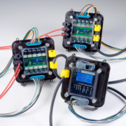 Copyright Infinitybox, LLC 2021. All Rights Reserved.
 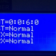 Copyright Infinitybox, LLC 2021. All Rights Reserved.
 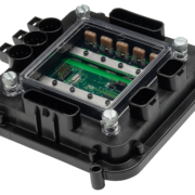 Copyright Infinitybox, LLC 2021. All Rights Reserved.