Reverse Lockout Solenoid
A customer just sent us pictures showing how he wired a switch into his transmission shifter to control his reverse lockout solenoid. He wanted to make sure that he couldn’t accidentally shift into reverse when he was in the upper gears. By using our Infinitybox wiring system, he was able to easily control this solenoid.
Ed K. is building a 1968 Pro-Touring Mustang fastback. He has transplanted a Coyote engine from a 2014 Mustang and mated it to a Tremec T56 6 speed transmission, feeding a Ford 9 inch rear end for the drivetrain. He is using our 20-Circuit Kit with inLINK, inRESERVE and inMOTION to wire his car.
The Tremec transmission is outfitted with a solenoid lockout feature that further pre-loads an already compressed spring acting on the shift gate to prevent accidentally engaging reverse while downshifting from 6th gear to 5th gear, which would be catastrophic. In order to engage reverse, when desired, this solenoid must be energized to remove this extra spring pre-load. Typically, this solenoid is energized by a body controller when the car is moving at 5 miles per hour or less to allow a shift into reverse. Ed wanted a simpler way to engage this reverse lockout solenoid in his 1968 Mustang.
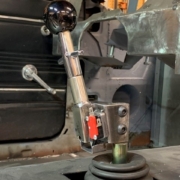
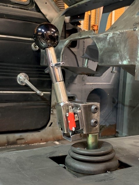
Ed modified the shift lever to add a microswitch to it. When he pulls up on the shifter handle, the switch closes. He can use this switch to control his reverse lockout solenoid.
Ed picked the OPEN output on his front POWERCELL to power his reverse lockout solenoid. The OPEN outputs on your configuration sheet can be used for practically anything. They are auxiliary outputs for any additional electrical accessories that you may have on your car. Click on this link to learn more about OPEN outputs.
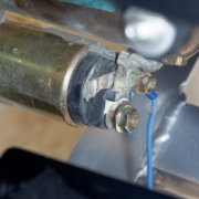
Ed connected this open POWERCELL output wire to the solenoid, then grounded the other side of the solenoid wiring.
Next, Ed found the MASTERCELL input that corresponds to the OPEN output that he used. Your configuration sheet shows you which input and output wire colors go together. Ed connected this MASTERCELL input to the normally open terminal on his shifter switch. Then he connected the common terminal of the switch to ground. When he pulls up on the reverse handle, the switch closes. This connects the MASTERCELL input to ground. The MASTERCELL sends a command to the front POWERCELL to turn on the output, which energizes the reverse lockout solenoid. This pulls back the reverse gate, which lets him shift into reverse. Here is a simple wiring diagram showing how this was connected.
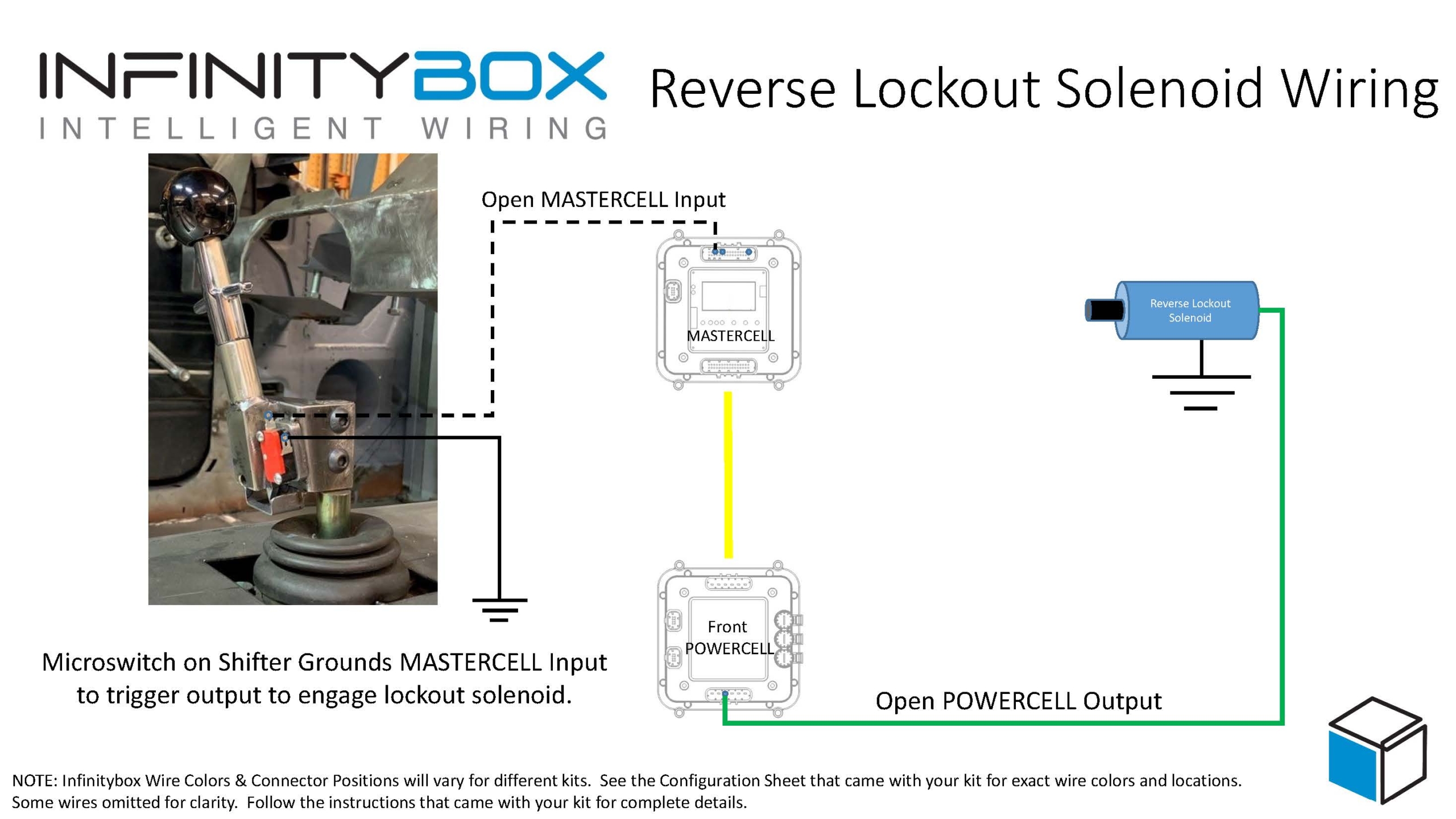
Picture of simple schematic showing how to control a reverse lockout solenoid with the Infinitybox system.
Ed was able to wire his reverse lockout solenoid easily with our Infinitybox system. He didn’t have to add any relays to his car to do this. He was able to use the flexibility and expandability of our system to get what he needed in his car.
You can download a PDF version of this wiring diagram by clicking this link.
Click on this link to learn more about what the Infinitybox system can do for your restoration, street rod, resto-mod, kit car or pro-touring build.
 Copyright Infinitybox, LLC 2021. All Rights Reserved.
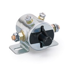

 Copyright Infinitybox, LLC 2021. All Rights Reserved.
 Copyright Infinitybox, LLC 2021. All Rights Reserved.