 Copyright Infinitybox, LLC 2021. All Rights Reserved.
 Digital Guard Dawg PBS II Wiring
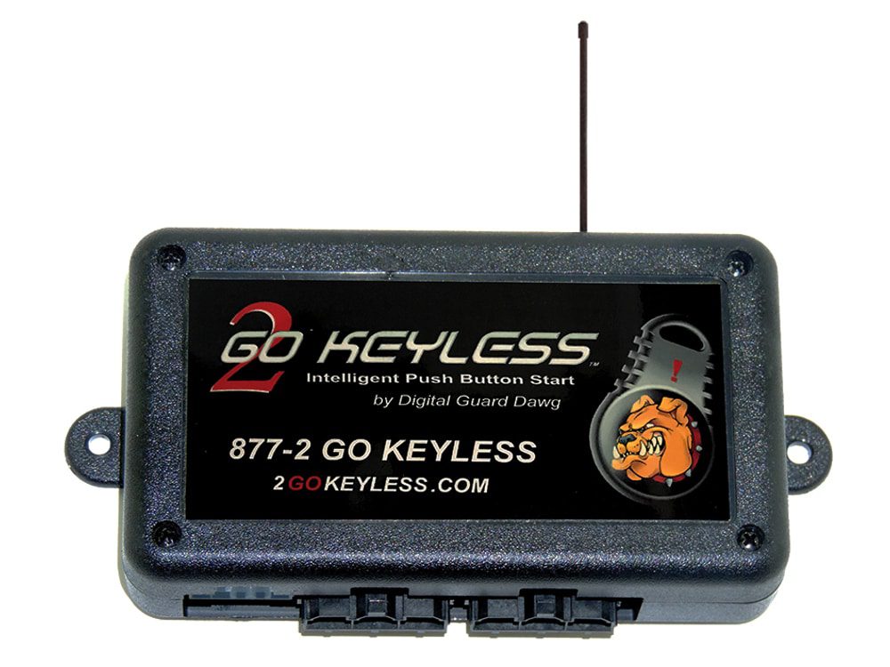
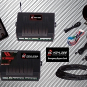
Picture of the Digital Guard Dawg PBSII System
Our Infinitybox system plays nicely with any other electrical accessory that you would want to install in your hot rod, restoration, resto-mod, street rod, kit car or pro-touring build. This blog post is going to cover the Digital Guard Dawg PBS II wiring. It will show you how to connect the PBS II push-button start PKE module to your Infinitybox 20-Circuit Kit. This gets you the passive keyless entry features of the Digital Guard Dawg PBS II paired with the power and flexibility of the Infinitybox system. We have blogged before about wiring their iKey system into our Infinitybox system. You can see that post by clicking this link.
Before you go anywhere, it is very important that you thoroughly read and understand the manual for the Digital Guard Dawg PBS II. You can access that by clicking this link. Once you are familiar with their instructions, it is time to get into the Digital Guard Dawg PBS II wiring and the Infinitybox system. This blog post is only going to cover the connections between the PBS II and the Infinitybox system. Follow their instructions for all constant power and ground connects. Also follow their instructions for wiring their push to start button and their training button.
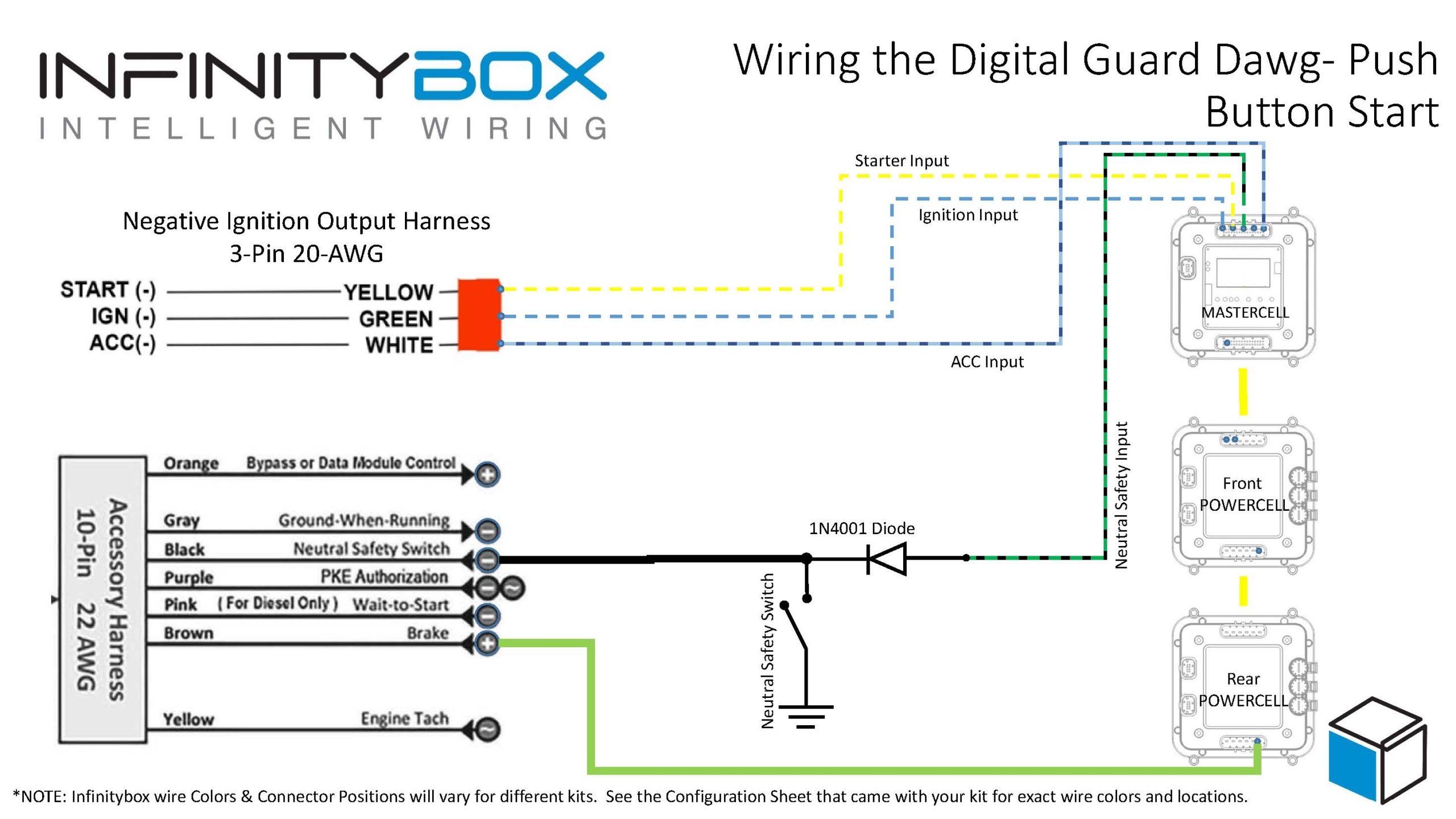
The PBS II will give you passive keyless entry (PKE) capability for your car. As you approach the car, the PBS II system detects the presence of the key fob in your pocket. It engages the ignition and lets you start the car. The PBS II connects to the MASTERCELL of your 20-Circuit Kit and replaces the need for a traditional ignition/start switch. This diagram shows the necessary connections that you need to make.
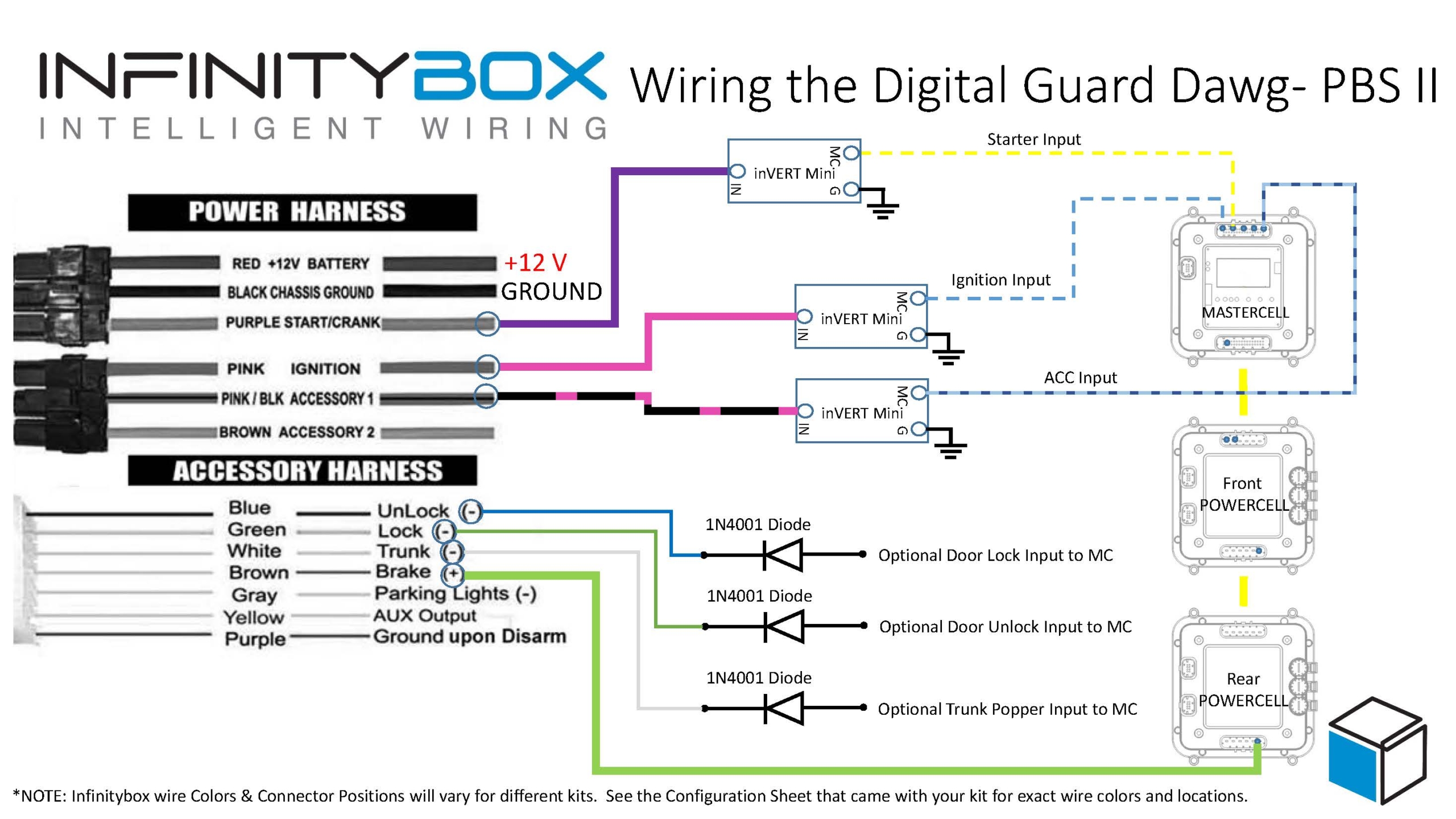
Picture of Infinitybox wiring diagram showing to to wire the Digital Guard Dawg PBSII
The PBS II will send the signals to the MASTERCELL for the ignition and the starter. When the MASTERCELL sees these inputs turn on, it will send the required signals to the POWERCELLs to power your ignition and starter outputs. The PBS II wires for the ignition and starter are positive signals. The MASTERCELL requires ground triggers for the inputs so you will need to wire in our inVERT Minis to buffer their positive signal. You can learn more about the inVERT Mini and purchase them at this link. The diagram above shows where to put the inVERT Minis in the circuit.
The PBS II also needs a signal to know that you are stepping on the brake pedal. This signal must be positive 12-volts. Since our MASTERCELL inputs work by being triggered to ground, you cannot get this positive brake signal from the brake pedal switch directly. You need to get this from the POWERCELL output for the brake lights. You can simply splice into the brake light output on the rear POWERCELL. Alternately, you can use an OPEN output on the front POWERCELL as the brake pedal trigger. You would wire the corresponding input to your OPEN output to the brake pedal switch, in parallel with your usual brake light input. Doing it this way keeps the run of wires in the car short.
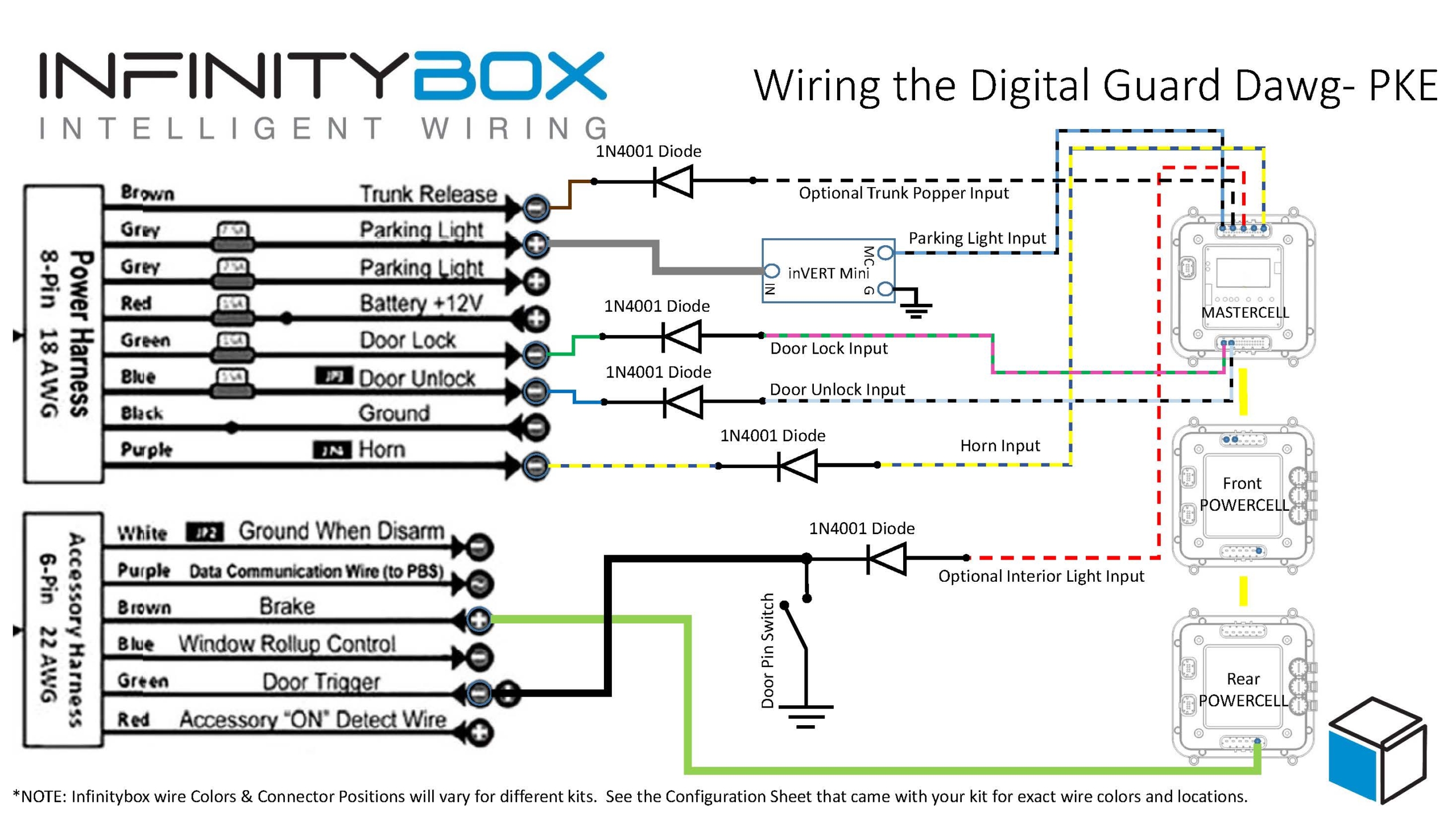
The PBS II also has provisions to control door locks and trunk poppers. If you purchased inMOTION for your Infinitybox system, you can wire the MASTERCELL inputs for your door locks to the Unlock and Lock signals on the PBS II Accessory Harness. We recommend using a diode to isolate the MASTERCELL from any stray voltages that may exist in the PBS II. This diode should be a 1N4001 and must be oriented per the diagram above. These inputs will not work if the diodes are installed incorrectly.
The PBS II also has provisions to control a trunk popper from their key fob. You can take any of the OPEN outputs on your rear POWERCELL to control you trunk popper. You would wire the corresponding MASTERCELL input to the white Trunk wire in their accessory harness. Just like the signals for the door locks, we recommend isolating the MASTERCELL inputs from the PBS II with a 1N4001 diode as shown in the wiring diagram.
You can download a PDF version of this wiring diagram by clicking this link.
Please contact our team if you have any questions about this Digital Guard Dawg PBS II Wiring diagram. You can reach out team by clicking this link.
 Copyright Infinitybox, LLC 2021. All Rights Reserved.