Atomic EFI
We’ve blogged before about how to power many different EFI systems with Infinitybox. Examples include the Ford Coyote ECU, the GM LS ECU, the Holley Dominator, the FAST EZ-EFI and many others. This post is going to cover how to wire the Atomic EFI system from MSD.
Here’s what MSD says about their Atomic EFI:
“The Atomic EFI provides the performance and driveability benefits that you expect from fuel injection. Quick starts, smooth idle and great throttle response just to name a few. Combine the fact that the Atomic will support ignition timing through the ECU and you have a win-win combination. Initial timing is handled through a compact handheld monitor where you simply answer a few car guy questions about your engine and you’re off and running!”
Just like any other EFI system, wiring it with our Infinitybox 10 or 20-Circuit Harness Kit is very easy. You get several advantages over wiring with a traditional wiring harness.
- You run less wire in the car. The ECU sits behind the dash and connects to the MASTERCELL. The cooling fan and fuel pump are wired to their local POWERCELLs. You’re not running wires from the ECU all over the car.
- You can eliminate the need for relays and external fuse holders. The POWERCELLs are your relays. Each output is fused inside the POWERCELL.
- You get security and immobilizer functions in your Infinitybox system. You don’t have to add a separate alarm system to keep unwanted people from starting your car.
- You can get cooling fan timing and delays right in the Infinitybox system. You don’t need to add separate controller modules.
Before you connect your Infinitybox system to your Atomic EFI system, you must completely understand the instructions from MSD. Click on this link to get to the manual for their Atomic EFI PN 2910 – Throttle Body Kit. This post is going to show you how to wire the key-on power to the Power Controller. It will also show you how to wire ground, constant battery power, the fuel pump trigger and the cooling fan trigger. See the MSD manual for the rest of the electrical connections to their harness.
This diagram will show you the details of wiring your MSD Atomic EFI system to your Infinitybox system.
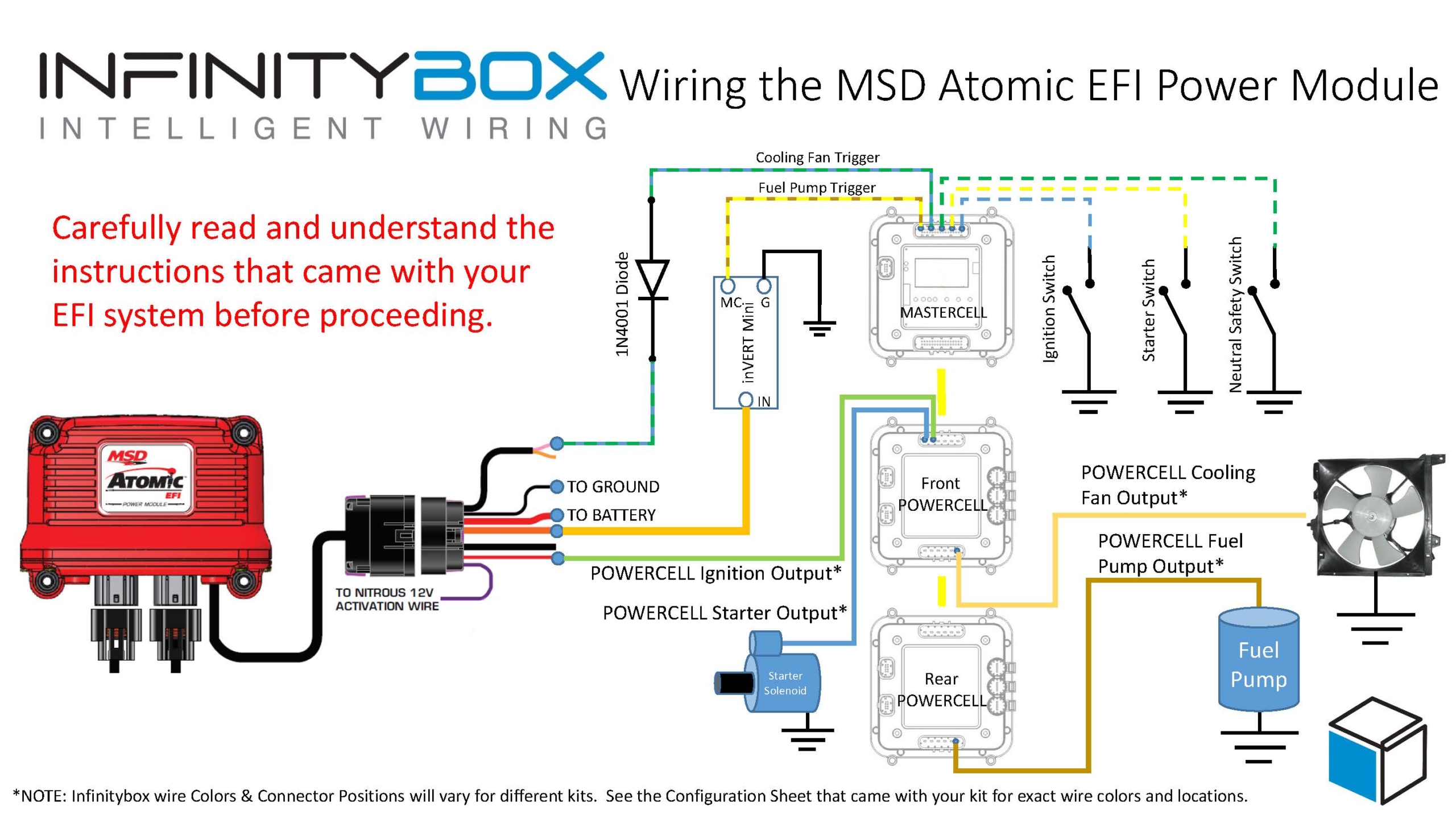
Picture of wiring diagram showing how to wire the MSD Atomic EFI Power Module with the Infinitybox 20-Circuit Kit
To start, you need to connect constant power and ground to the MSD Power Module harness. MSD recommends connecting the large red wire directly to the battery. The ground wire should get connected to the chassis through a metal-to-metal connection.
The small red wire is the key-on power wire to the Power Module. When you key is in the on or start position, you should have battery voltage on this wire. The small red wire in the MSD harness is going to connect to the ignition output wire on your POWERCELL. Check the configuration sheet that came with your kit for the correct color and connector orientation for all of the POWERCELL connections.
There are two wires in the MSD Power Module harness for cooling fan triggers. The pink wire is the primary and the tan wire is for the secondary cooling fan. Both of these wires are intended to ground a relay coil to turn on the fan. You can connect them directly to the MASTERCELL inputs. The MASTERCELL inputs are expecting a ground trigger to turn on the inputs. You must put a diode in-line between the Power Module fan trigger wires and the MASTERCELL input wires. This should be a 1N4001 diode. The orientation of this diode is critical for this to work properly. See the diagram above for correct orientation of the diode.
Once you have the MASTERCELL input wired to the Power Module for the cooling fan trigger, you need to connect the POWERCELL output to your cooling fan. See the configuration sheet that came with your kit for the proper wire color. If you want to use a secondary cooling fan, you can use any of the OPEN outputs on your system.
There is a large orange wire on the Power Module harness for the fuel pump. This wire puts out a positive signal for the fuel pump. You will need to invert this signal to a ground signal to work properly with the MASTERCELL. You can use a relay to do this. This link will show you how. The easier way to do this is to use one of our inVERT Mini‘s.
Once you have the MASTERCELL input for the fuel pump properly connected to the MSD Power Module fuel pump output, you need to wire your POWERCELL output to your fuel pump. Again, your configuration sheet will shows which wire to use.
That’s it. All of your relays and fuses are built into the Infinitybox system. Once you follow these steps, you’re ready to power up your system and start tuning the engine.
You can download a PDF copy of this wiring diagram by clicking this link.
 Copyright Infinitybox, LLC 2021. All Rights Reserved.