Posts

Jeep CJ7 Wiring Series- MEGA Fuse Location

Over the next few videos, we’re going to continue our theme on good planning.  Specifically, we’re going to talk about picking the best locations for the major components that come with your Infinitybox system.  We’re installing our 20-Circuit Kit with inLINK and inRESERVE in our 1979 CJ7.  To get the most out of our install, we want to pick the best locations for the MASTERCELL, the front & rear POWERCELLs, the MEGA fuse holder and the inRESERVE solenoid.  We’ve broken this up into 5 different videos, talking about what you need to consider for each part.  This video covers picking the best location for the block of MEGA fuses that comes with your 20-Circuit Kit.


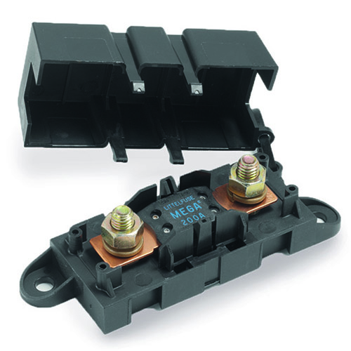
Everything starts with running primary power from the battery.  The POWERCELLs get powered by cables that connect back to the positive terminal of the battery.  These cables need to be protected against short circuits by fuses.  Your 20-Circuit Kit includes a block of 4 high-current MEGA fuses to protect the four 8-AWG cables that bring battery power to the POWERCELLs.  If one of these cables was to short to ground, the MEGA fuse becomes the weakest link in the electrical chain.  The fuse opens to protect the cable from damage.  You want the MEGA holder to be mounted as close to the battery as possible to minimize the length of unprotected cable.

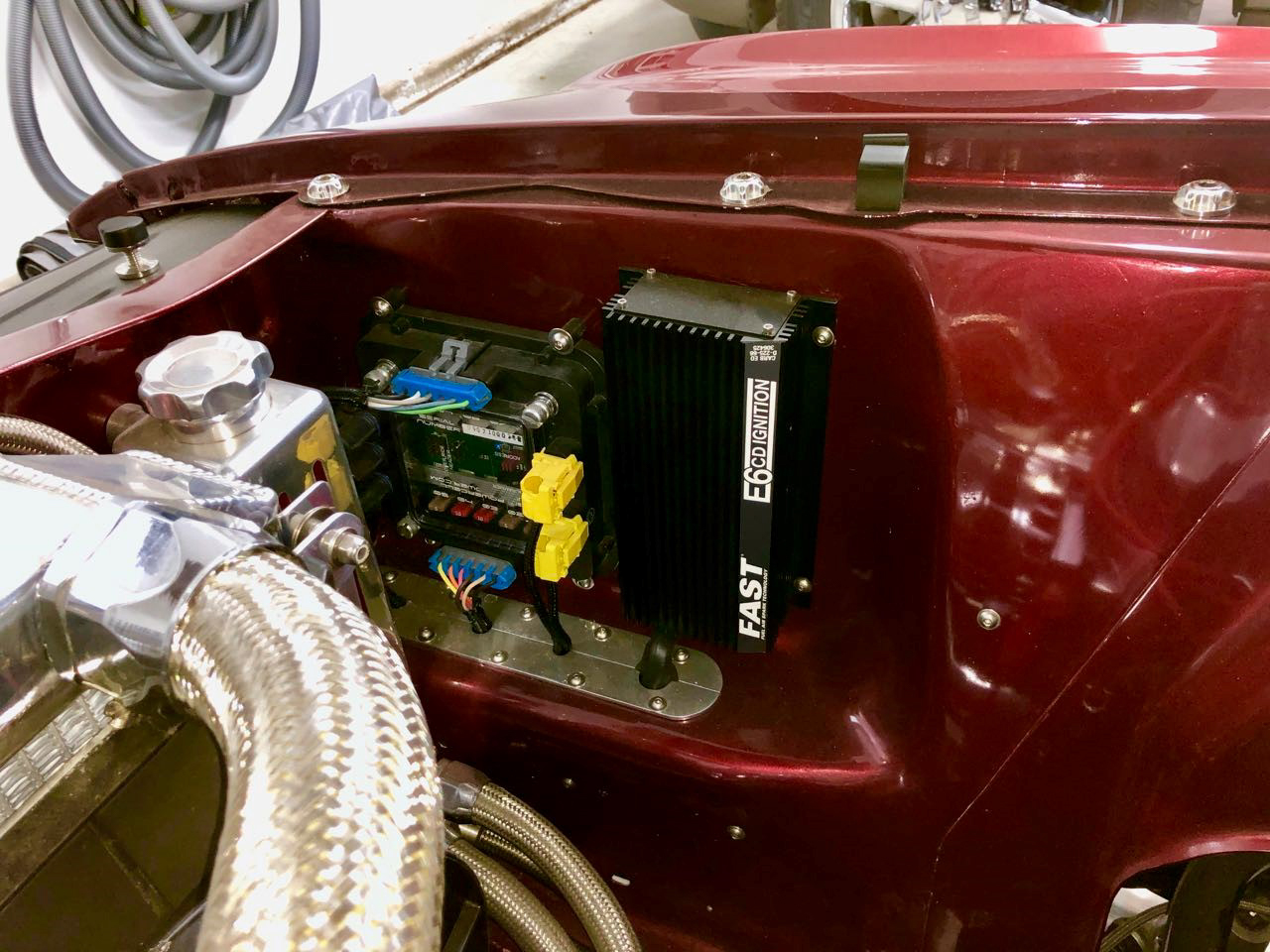
We’re going to mount the MEGA fuse block right in front of the battery, under the hood.  There is a flat spot on the inner passenger fender that would be a great place.  It is a short run of cable from the positive terminal to this location and we can easily route the 8-AWG power cables to the front & rear POWERCELLs.  Watch this video to learn more about these and see where we’re mounting the MEGA fuses in the Jeep.

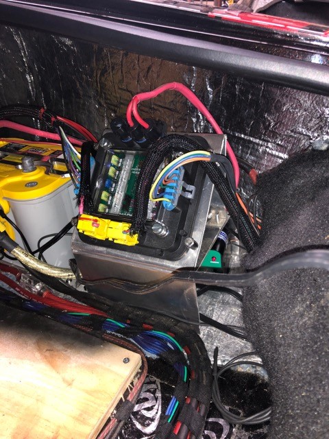
We are also installing our inRESERVE battery management solenoid in the Jeep.  The best location for the inRESERVE solenoid is usually right next to the block of Mega fuses.  This picture shows you how the Mega fuses go hand in hand with the inRESERVE battery management kit.

This diagram will show you the overview of the Mega fuses in the Jeep and show you how they connect to the battery, the inRESERVE solenoid and the 8-gauge power cables that feed each POWERCELL.

Infinitybox Jeep CJ7 Wiring Diagram- Cell Locations and Primary Power Routing

Infinitybox Jeep CJ7 Wiring Diagram- Cell Locations and Primary Power Routing

You can download a PDF copy of this diagram by clicking this link.

Picking the best location for the MEGA fuse holder will get you a safe and reliable electrical system in your car or truck.  It will also make running the power cables to your POWERCELLs easier if you plan in advance.  Keep watching for more in our 1979 Jeep CJ7 Install Series.

Be sure to subscribe to our YouTube channel and click the bell icon so you get notified when we post new videos in the series.

Click on this link to get to the main page for the 1979 Jeep CJ7 wiring project.  You can find all of the videos on one place there.  

You can also click here to contact our technical support team with any questions about your car or truck wiring project.  

1969 Chevelle wired with the Infinitybox system

1969 Chevelle Wired with Infinitybox

Front of 1969 Chevelle wired with the Infinitybox system

Front of 1969 Chevelle wired with the Infinitybox system

Here’s another great customer car wired with our Infinitybox system.  Matthew W sent us these pictures of his finished 1969 Chevelle.  He’s had this 1969 Chevelle a long time.  This is the first car that he ever got to change a tire on.

1969 Chevelle wired with the Infinitybox system

1969 Chevelle wired with the Infinitybox system

He has a 383 stroker engine in it with Aluminum heads.  It is fed through an Edelbrock dual quad carb set up.  He has an MSD ignition box giving it spark.  He has the Vintage Air Front Runner system with their Gen-IV system.

Engine bay of 1969 Chevelle wired with the Infinitybox system

Engine bay of 1969 Chevelle wired with the Infinitybox system

He wired the car with our Infinitybox 20-Circuit Kit.  He added inLINK for security features.  He also add inRESERVE to manage his trunk-mounted battery.

You can see this picture of his rear POWERCELL and the inRESERVE solenoid protecting his battery.  The rear POWERCELL is mounted conveniently in the rear, right corner of the car.  This is very accessible if he needs to change a blown fuse, the runs of wire are short and it can be hidden neatly behind the custom trim piece that he made.

Rear POWERCELL and inRESERVE solenoid installed in 1969 Chevelle wired with the Infinitybox system

Rear POWERCELL and inRESERVE solenoid installed in 1969 Chevelle wired with the Infinitybox system

Congratulations to Matthew for finishing his car.  It is spectacular and we are proud to be a part of his build.

Interior of 1969 Chevelle wired with the Infinitybox system

Interior of 1969 Chevelle wired with the Infinitybox system

Click here if you’d like to learn more about wiring your car or truck with our Infinitybox system.


inLINK Radio Board Install

Our inLINK Wireless Control Module is the most popular accessory that guys add to their Infinitybox 20-Circuit Kit.  With inLINK, you can control the functions of your Infinitybox system through a simple key fob.  inLINK seamlessly integrates into your MASTERCELL with no external boxes of modules.  You can enable and disable security.  You can control your lights.  You can pop your doors.  You get a ton of flexibility.

If you buy inLINK with your 20-Circuit Kit, we pre-install it for you at the factory.  If you don’t buy inLINK up front, you can add it at any time.  Installing it to your MASTERCELL is very simple.  You only need a screw driver.  No software updates are needed.  The MASTERCELL is pre-programmed to talk to the inLINK radio receiver board.

The inLINK kit includes the inLINK Radio Receiver Board, two spacers, two screws and two of the inLINK key fobs.  The following instructions show you how to install the inLINK Radio Receiver Board into the MASTERCELL.

STEP 1- Disconnect the MASTERCELL.

inLINK Installation- Figure 01

inLINK Installation- Figure 01

Unplug the MASTERCELL input harnesses and the CAN cable as shown in Figure 1.  Remove the MASTERCELL from the car.

STEP 2- Remove the Screws from the Back of the MASTERCELL.

inLINK Installation- Figure 02

inLINK Installation- Figure 02

Turn over the MASTERCELL so the inSIGHT screen is facing down as shown in Figure 2.  Remove all 8 screws from the back of the MASTERCELL with a Phillips screwdriver.  Put these screws in a safe place.

STEP 3- Remove the Back of the MASTERCELL

inLINK Installation- Figure 03

inLINK Installation- Figure 03

Once the screws are removed, carefully separate the plastic housing (A) from the back cover (B) as shown in Figure 3.  Carefully separate the housing and back cover of the MASTERCELL unit by first turning the unit upside down and gently placing your fingers in the input connector shells.  Gently press up on the connector pins while holding the plastic housing (A) with your thumbs until the back cover is separated from the housing.  Be sure to keep the plastic housing facing down to keep the buttons in place. If they do fall out, locate all five buttons and put them to the side.  Set aside the plastic housing, keeping it upside-down so that the buttons do not fall out.

STEP 4- Prepare the inLINK Radio Receiver Board.

inLINK Installation- Figure 04

inLINK Installation- Figure 04

Disconnect the daughter board (A) in Figure 4 from the sockets (C) on the radio receiver board (B).  Be careful not to bend the pins when removing.

STEP 5- Place the Spacers on the MASTERCELL Board.

inLINK Installation- Figure 05

inLINK Installation- Figure 05

Place the two clear spacers (A) on the board (B) as shown in Figure 5.  The two spacers should go over the holes in the MASTERCELL printed circuit board.

STEP 6- Install the inLINK Radio Receiver Board.

inLINK Installation- Figure 06

inLINK Installation- Figure 06

While keeping the spacers in place, carefully align the pins on the radio receiver board (A) with the header on the MASTERCELL board (B) as shown in Figure 6.  Insert the radio board pins (A) into the MASTERCELL connecting header (B) and push in the board until the plastic connector on the radio receiver board meets with the header on the MASTERCELL board.  Ensure that the spacers are still aligned with the holes prior to securing the radio receiver board with screws. If the spacers are not aligned, CAREFULLY put them back in place using a small tool.

STEP 7- Install inLINK Board Screws.

inLINK Installation- Figure 07

inLINK Installation- Figure 07

Fasten the radio receiver board to the MASTERCELL board by inserting the included screws into the holes as shown in Figure 7 and tighten the screws until the board is secure.  DO NOT OVER-TIGHTEN THESE SCREWS.

STEP 8- Reinstall the inLINK Daughter Board.

inLINK Installation- Figure 08

inLINK Installation- Figure 08

Align daughter board (A) pins with the top row of holes on the radio board header (B) as shown in Figure 8 and insert pins. Push in the daughter board until both headers are flush.  Wrap antenna wire (D) in Figure 7 and Figure 8 in a large circle around the inSIGHT diagnostic module (C) in figure 8. Make sure that it does not interfere with the pins or plastic mating surfaces.

STEP 9- Replace the MASTERCELL Buttons

inLINK Installation- Figure 09

inLINK Installation- Figure 09

If any of the MASTERCELL buttons fell out of the housing, reinstall them as shown in Figure 9.

STEP 10- Reassemble MASTERCELL.

inLINK Installation- Figure 10

inLINK Installation- Figure 10

Keeping the housing upside-down, insert the MASTERCELL board and back cover (A) as shown in Figure 10 by aligning the input pins with the correct holes in the housing. DO NOT flip over the front cover as this will cause the buttons to fall out. Gently press the cover down until all pins have gone through their corresponding openings
on the housing and the back cover fits snugly in place.

STEP 11- Reinstall Screws on Back Cover of MASTERCELL.

inLINK Installation- Figure 11

inLINK Installation- Figure 11

Insert screws back into the holes on the back cover and tighten until the cover is securely fastened.  DO NOT OVER-TIGHTEN THESE SCREWS.

STEP 12- Reinstall MASTERCELL In Car.

inLINK Installation- Figure 12

inLINK Installation- Figure 12

Mount MASTERCELL input unit back into your vehicle and plug all connectors back into their proper location as shown left in Figure 12.

Power up your Infinitybox system once you have completed these steps.  You will need to train your inLINK key fobs to the MASTERCELL after the Radio Receiver Board has been installed.  Click on this link to get to the instructions to train your inLINK Key Fobs.

Contact our technical support team if you have any questions on how to install your inLINK module in your Infinitybox 10 or 20-Circuit Kit.

1955 Chevy Bel Air wired with the Infinitybox System

1955 Chevy Bel Air- Great 8 Winner

Our Infinitybox team is thrilled to be a part of Bob Matranga’s 1955 Chevy Bel Air.  This car was awarded as one of the Great 8 winners for the 2020 Ridler Award at the Detroit Autorama.  The car is appropriately named Brute Force.

1955 Chevy Bel Air wired with the Infinitybox System

1955 Chevy Bel Air wired with the Infinitybox System

Bob and his team built a stunning 1955 Chevy Bel Air.  You could spend hours looking at all of the details in this car.  From the engine, to the chassis, to the one-off lights, to the leather treatment to the emblems, this is an impressive car.

1955 Chevy Bel Air wired with the Infinitybox System

1955 Chevy Bel Air wired with the Infinitybox System

1955 Chevy Bel Air wired with the Infinitybox System

1955 Chevy Bel Air wired with the Infinitybox System

1955 Chevy Bel Air wired with the Infinitybox System

1955 Chevy Bel Air wired with the Infinitybox System

You can see an interview with Bob going through the details of the car here.  Thanks to EClassic Autos for the video content.

1955 Chevy Bel Air: Great 8 Winner at 2020 Detroit Autorama from eclassicautos on Vimeo.

Bob’s team started with our Infinitybox 20-Circuit Kit to wire the car.  From there, they added inMOTION to control their power locks and power windows.  They added inLINK for remote control from a key fob.  inRESERVE for active battery management.  inTOUCH NET so they can control the car from a tablet or smart phone.  And inVIRONMENT so they can control their Vintage Air Gen-IV from their touch screen.  They have the cells strategically located in the car to optimize the wiring harness and get them the most features.

We had a chance to talk to Chris Brown of Brown Auto Design at the Autorama.  Chris is the mastermind behind the design of this car.  He mentioned to us that he had very limited room to run wires in the car.  Using the Infinitybox system made wiring the car much easier for him and his team.

1955 Chevy Bel Air wired with the Infinitybox System

1955 Chevy Bel Air wired with the Infinitybox System

We are very proud to be a part of this project.  Congratulations to Bob and the entire team at Matranga Hot Rods for making it to the Great 8.

Click on this link to contact our team to learn more about wiring your car with our Infinitybox system.

1955 Chevy Bel Air wired with the Infinitybox System

1955 Chevy Bel Air wired with the Infinitybox System

Fixing inCODE Software Driver

Our inCODE Programmer is the tool that you need to load custom configurations into your Infinitybox system.  It connects your computer to your MASTERCELL to let you make changes.  Our technical support team makes the changes for you.  You use inCODE to load these changes into your system.  This link will take you to the basics on using inCODE.

If you carefully read the instructions for using inCODE, you will see a big and bold message that says to not plug the inCODE programmer into your computer until after you have loaded the Embed Inc software.  When you plug the inCODE programmer into your computer, Windows automatically installs the drivers that it needs to make it work correctly.  When you install the Embed Inc software, it installs the drivers for inCODE and leaves instructions for Windows so it knows what to do with inCODE.  If you plug inCODE into your computer before you install the Embed Inc software, your computer takes a guess at what the inCODE programmer is and assigns a random driver to it.  You will get an error when you try to load code onto your system if this happens.

Reinstalling the Embed Inc software will not solve this issue since Windows has already assigned the wrong driver to the inCODE hardware.  You need to remove the inCODE programmer from your Device Manager and let Windows recognize it again.  This quick video will help you go through this process.

Please click on this link to contact our technical support team if you have any additional questions about setting up your inCODE programmer.


1970 Mustang Infinitybox Wiring

Here’s another great example of a customer car wired with our Infinitybox system.  Paul L. wired this beautiful 1970 Mustang with our 20-Circuit KitinLINK and inMOTION.  Paul just sent us pictures showing off the finished car and how he installed his Infinitybox system.

This picture shows the center console of his car.  You can see the MASTERCELL and the inMOTION cell located in the frame of the center console.  The MASTERCELL connects to all of his switches.  The inMOTION cell controls the motion of his power windows and door locks.

MASTERCELL and inMOTION cell in a 1970 Mustang wired with the Infinitybox system

MASTERCELL and inMOTION cell in a 1970 Mustang wired with the Infinitybox system

You can see in this picture how seamlessly these cells disappear into the interior of the car.

Interior of a 1970 Mustang wired with the Infinitybox system

Interior of a 1970 Mustang wired with the Infinitybox system

His engine looks great under the hood.

Front POWERCELL Mounted Under the Hood of a 1970 Mustang Wired with the Infinitybox System

Front POWERCELL Mounted Under the Hood of a 1970 Mustang Wired with the Infinitybox System

He relocated the battery to the trunk of the car.  He used this space for his ignition system and his front POWERCELL.  This POWERCELL location is great because it makes most of his front wiring short and easy to install.  His headlights, high-beams, turn signals, running lights, starter solenoid, ignition power, cooling fan and horn are all powered from this location.

Front POWERCELL Mounted Under the Hood of a 1970 Mustang Wired with the Infinitybox System

Front POWERCELL Mounted Under the Hood of a 1970 Mustang Wired with the Infinitybox System

His rear POWERCELL is located in the trunk.  This makes wiring his brake lights, turn signals, rear running lights, fuel pump, trunk popper and other accessories very easy.

We did some simple customization of this code to get him extra features.  He’s controlling his door locks from outputs on inMOTION.  His doors lock and unlock when he enables and disables security from his inLINK key fob.  He is also using a POWERCELL output to operate a solenoid to pop his trunk.  We programmed a button on his inLINK key fob to pop the trunk.  He also wanted an output on his rear POWERCELL to turn on with ignition.  These are all very simple changes to our system.

The finished wiring is simple and elegant.  We thank Paul L. for sending these pictures.  We’re proud to be a part of his project.

Click this link to contact our team to learn more about wiring your car or truck with our Infinitybox system.

Chevy S10 Show Truck wired with the Infinitybox system.

Chevy S10 Show Truck

We occasionally get customers dropping by our office to show off their projects.  Chris C. brought his Chevy S10 show truck by the Infinitybox HQ to show us what he did and to get a few quick code changes.  He and his girlfriend were on their way to a truck show near Indianapolis.

Chevy S10 Show Truck wired with the Infinitybox system.

Chevy S10 Show Truck wired with the Infinitybox system.

Chris really loves this truck.  It is the first car that he ever owned.  He had done some modifications to it but it was totaled in an accident.  He started over from scratch and it has become something pretty cool.

First, he dropped in a bored-over Chevy 350.  It has a great rumble to it.  Then, he channeled and bagged it.  With the air dumped, it sits on its frame rails.  Then, there are the little details.  The doors and tail gate are shaved.  The interior, bed and engine compartment are done up with accent LED’s.  Lastly, he has a simple 150 hp of Nitrous to keep things interesting.

He chose to yank out the original OEM wiring and start over from scratch with our Infinitybox System.  He started with our 20-Circuit Kit, added inMOTION for the windows and lastly upgraded to inTOUCH NET to control the truck from phone.

inTOUCH NET really makes this truck.  His phone is the key to the truck.  He uses it to disable security, pop the doors, control the lights and the windows.  He can push a button to dump the air solenoid to drop the truck to the ground.  Also, we modified his code to automatically roll up the windows when he enables security.  It will be a hit at the show this weekend.

He proudly shows off the wiring in the truck.  His front POWERCELL is mounted right on the firewall.  The Infinitybox system is designed to handle the roughest environments so this location is fine.  This also makes wiring the front of the car very easy.  All of his runs of wire are very short.

Front POWERCELL under the hood of a Chevy S10 Show Truck wired with the Infinitybox system.

Front POWERCELL under the hood of a Chevy S10 Show Truck wired with the Infinitybox system.

He has his rear POWERCELL mounted to the inside wall of the truck’s bed.

Rear POWERCELL in a Chevy S10 Show Truck wired with the Infinitybox system.

Rear POWERCELL in a Chevy S10 Show Truck wired with the Infinitybox system.

Rear POWERCELL in bed of a Chevy S10 Show Truck wired with the Infinitybox system.

Rear POWERCELL in bed of a Chevy S10 Show Truck wired with the Infinitybox system.

Finally, he has his MASTERCELL and inMOTION cells prominently displayed between the two seats in the cab.

MASTERCELL and inMOTION Cell in a Chevy S10 Show Truck wired with the Infinitybox system.

MASTERCELL and inMOTION Cell in a Chevy S10 Show Truck wired with the Infinitybox system.

Contact our team if you want to learn more about how our Infinitybox System can simplify the wiring in your car or truck plus give you features that no other electrical system can.  Keep watching our blog for more examples of how our customers are wiring with Infinitybox.

1968 Charger wired with the Infinitybox system

1968 Charger Install

We love getting pictures of finished cars from our customers. Most of our customers send the glamour shots of the cars all waxed up, looking pretty. Some of our customers like to show off the details that the rest of the world doesn’t get to see. The detail pictures are our favorites because they show how our customers wired their cars with our Infinitybox system. We received a great set of detailed pictures from Russ L. who installed our Infinitybox system in his 1968 charger. These pictures are great because they show how be mounted the cells in the car.

For his Charger, Russ purchased our 20-Circuit Kit with inMOTION and inLINK. This 20-Circuit is powering all of the primary electrical functions in the car including his ignition, starter, fuel pump, cooling fan, horn and all lights. He’s using inMOTION to control his power windows and power door lock. inLINK lets him enable and disable security, unlock his doors and control his lights remotely.

For his 1968 Charger install, Russ started by mounting his MASTERCELL. He was looking for the right location in this car. He wanted a place that was close to his switches to keep the input wires short. He also wanted a place that would let him easily run the CAN cable through the car. He found that the center console was the best location. He built a false bottom under the arm rest to hide the MASTERCELL. He can easily access it for troubleshooting and diagnostics. The CAN cable runs from the rear of the car right through the center console so it made that part of the wiring very easy. The input wires for the MASTERCELL run forward to the switches on the dash. He has a simple hole with a grommet to run the switch wires out of the arm rest. This picture shows his MASTERCELL mounted in the center console of this 1968 Charger.

Another shot of the Infinitybox MASTERCELL in a 1968 Charger wired with the Infinitybox system

Another shot of the Infinitybox MASTERCELL in a 1968 Charger wired with the Infinitybox system

Russ chose to mount his front POWERCELL under the hood on the driver’s side fender near where the battery would normally be mounted. Our POWERCELLs are designed to survive the harsh under-hood environment in cars. They can withstand all of the temperature extremes, chemicals and vibration that can be found in the engine compartment. He fabricated a simple aluminum plate and mounted it to the fender with riv-nuts. The POWERCELL is mounted to this plate using nylock nuts so they will not vibrate loose. This picture shows the front POWERCELL mounted under the hood.

Russ mounted his rear POWERCELL and inMOTION cell in the trunk. This picture shows the finished trunk. You can see how clean it is.

Finished trunk of 1968 Charger wired with the Infinitybox system

Finished trunk of 1968 Charger wired with the Infinitybox system

Russ built an aluminum stand to mount his rear POWERCELL. He wanted to tip it at an angle so he could easily see the fuses and indicator lights on the POWERCELL when he removed the access panel in the trunk. The aluminum stand is mounted directly to the trunk floor using riv-nuts and he used nylock nuts again to bolt the POWERCELL to the stand. He also used this aluminum stand as a place to mount his Battery Tender so he can easily keep his battery topped off. This picture shows the POWERCELL mounted behind the removable panel.

Rear POWERCELL mounted in trunk of 1968 Charger

Rear POWERCELL mounted in trunk of 1968 Charger

This is a great location for the rear POWERCELL because he has easy access to it for troubleshooting or in case he needs to replace a fuse. It also keeps his runs of wire in the back of the car very short.

Russ mounted his inMOTION cell just like the rear POWERCELL on the driver’s side of the trunk behind a removable panel. He fabricated a similar aluminum mount to hold the inMOTION cell. This picture shows how he mounted his inMOTION cell in his 1968 Charger.

Infinitybox inMOTION Cell Mounted in Trunk of 1968 Charger

Infinitybox inMOTION Cell Mounted in Trunk of 1968 Charger

The finished product is clean, efficient and more powerful any any other wiring harness on the market. We thank Russ for sending these pictures and letting us share them. We know that he is proud of this car and we’re proud to be a part of it.

As a parting shot, Russ sent this picture showing that MOPAR runs in his veins. This picture shows his 1968 Charger lined up with his daily drivers.

1968 Charger with the rest of its MOPAR Brothers

1968 Charger with the rest of its MOPAR Brothers

Please click on this link to contact our technical support team to learn more about how you can wire your car or truck with our Infinitybox system.

Front shot of a 1978 Porsche 930 track car wired with the Infinitybox system

Porsche Track Car

We have a customer in Colorado who is building a 1978 Porsche 930 as a track car. He has spent three years working on getting this car right. He turned to our team at Infinitybox to get a wiring system that will handle the abuse of the track, eliminate weight and get him the functionality that he needs in the car.

He picked up a 20-Circuit Kit to handle all of the electrical functions in the car. This package gets him 20 switched circuits, 10 in the front and 10 in the rear of the car. Even though a race car wiring harness is pretty basic, there are still a lot of things that need to get switched. Infinitybox makes wiring these plus adding more down the road easier than a traditional wiring system.

He is just at the point of mounting his cells in the car. You can check out some of the install pictures below.

He has his MASTERCELL mounted just forward of the shifter so that he can access the inSIGHT diagnostics easily.

MASTERCELL mounted in 1978 Porsche 930

MASTERCELL mounted in 1978 Porsche 930 track car

He wants to keep his weight low so he is mounting his POWERCELLs close to what is is controlling. This eliminated a lot of wire in the car. Here is his front POWERCELL.

Front POWERCELL in 1978 Porsche

Front POWERCELL in 1978 Porsche track car

His rear POWERCELL is mounted right in the engine compartment. Again, this keeps his wire runs very short. All of the POWERCELLS are rated for environments up to 125 degrees Celsius.

Rear POWERCELL in 1978 Porsche 930

Rear POWERCELL in 1978 Porsche 930 track car

It is a beautiful car and it will be a powerful machine when it hits the track. We’ll post more as he continues to wire the car.  If you want to get more details on the car, click on this link. You can also follow his whole build thread by clicking this link.

Click on this link to contact our team to learn how Infinitybox can make wiring your car easier.

1978 Porsche 930

1978 Porsche 930 wired with Infinitybox


Picture of a 1940 Super Buick wired with the Infinitybox system

Buick Super Coupe

Our Infinitybox system has been used to wire and control the electrical system of some of the most beautiful cars out there.  This 1940 Buick Super Coupe is no exception.  As a brand, Buick has always been known for style and comfort.  Built by Aubrey K, this car is a great example of great engineering, dedication and craftsmanship.  He took the style and comfort of this Buick and added power and performance.  The Infinitybox team is proud to be a part of this project.  You can see the finished product here.

Sunset shot of a 1940 Buick wired with the Infinitybox system

Sunset shot of a 1940 Buick wired with the Infinitybox system

Side shot of a 1940 Super Buick wired with the Infinitybox system

Side shot of a 1940 Super Buick wired with the Infinitybox system

Rear 3/4 Shot of a 1940 Buick wired with the Infinitybox system.

Rear 3/4 Shot of a 1940 Buick wired with the Infinitybox system.

Picture of a 1940 Super Buick wired with the Infinitybox system

Picture of a 1940 Super Buick wired with the Infinitybox system

Interior shot of a 1940 Buick wired with the Infinitybox system

Interior shot of a 1940 Buick wired with the Infinitybox system

Aubrey wired the car with our 20-Circuit Kit.  He was looking for a simple electrical wiring system that would give him the control that he wanted.  He wanted modern convenience features in his 1940 Buick Super Coupe.  They added inTOUCH NET to control the entire car from a touch screen mounted in the dash.

Congratulations to Aubrey and his team for completion of a beautiful car.  This project has been in the works for a long time and the patience and attention to detail is evident.

Contact our sales or technical support team if you want to learn more about how our Infinitybox system can get you the latest electrical functions and features in your restoration, Pro-Touring build, resto-mod or kit car.  Click this link to get in touch with our team.