 Copyright Infinitybox, LLC 2021. All Rights Reserved.
 Routing the CAN Cable
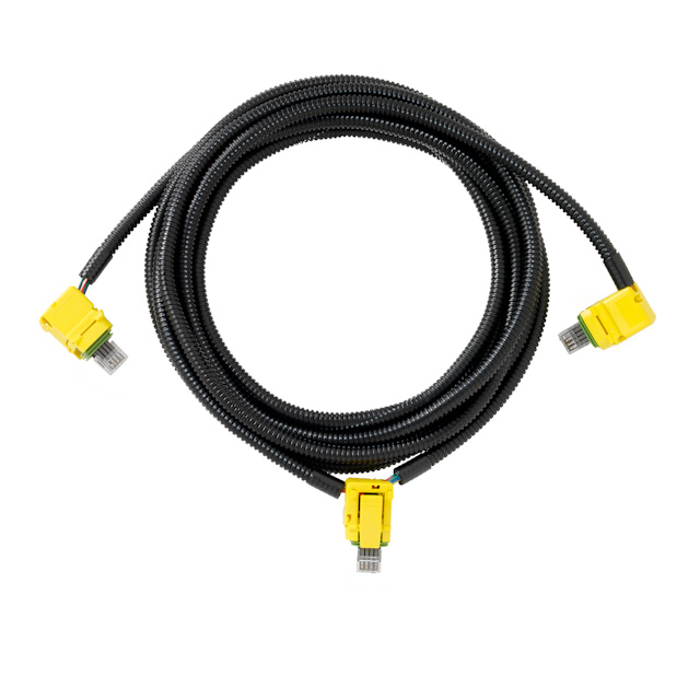
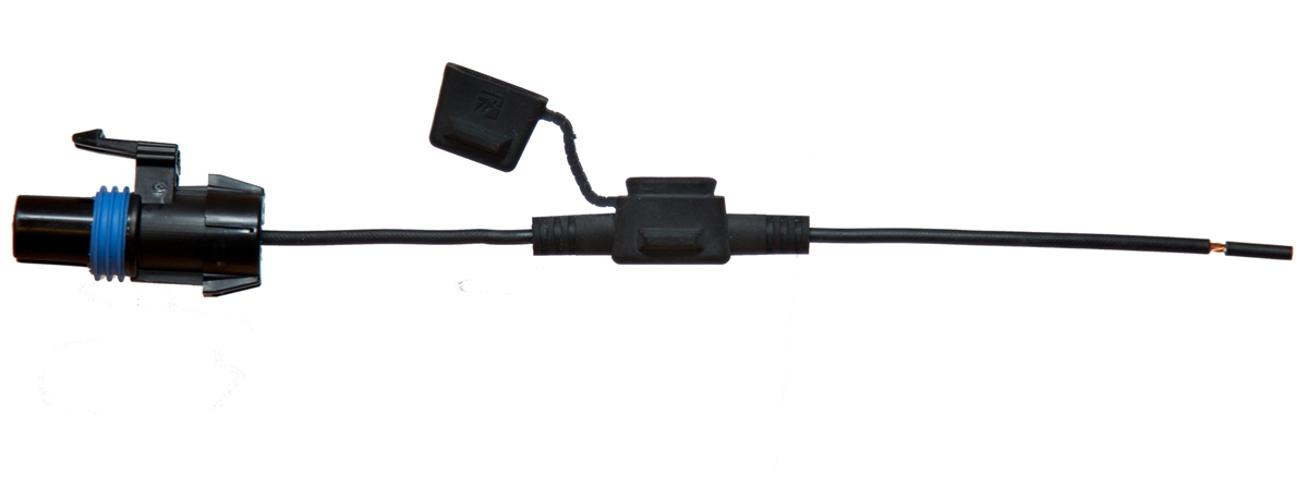
Picture of the Infinitybox 3-Way CAN Cable
Now it is time for routing the CAN cable through the 1967 Mustang. As we’ve described before, our Infinitybox system is different from a traditional wiring harness. We distribute switches and outputs throughout the car using our MASTERCELLs, POWERCELLs and inMOTION Cells. Instead of running power through large wires from every switch to the outputs, we pass data through small wires.
Our system works using something called CAN. That stands for Controller Area Network. It is the vehicle bus standard that was created to allow different controllers to communicate on a common protocol. You can read more about it by clicking this link. CAN has been around since the early 1980’s and is used in all modern passenger cars and commercial trucks.
The OEM’s use this technology to reduce weight of harnesses, simplify wiring and get more functions that you could from just a simple relay. Our Infinitybox system brings these exact features and benefits to anyone building a race car, restoring a vehicle or manufacturing commercial trucks.
Just because a system has CAN doesn’t necessarily mean that it can communicate with other CAN systems. The term CAN is pretty generic. It is the protocol that is the important part. For our aftermarket systems, we use a proprietary protocol that follows the CAN 2.0b standard. This lets us get much more control and features in our systems. For our commercial vehicle systems, we use J1939. This lets our hardware communicate with other J1939 peripherals and systems in the vehicle.
The CAN signals are passed between the MASTERCELL, POWERCELLs, inMOTION Cells and other modules through two wires in the CAN cable. Once a second, the MASTERCELL sends a command out to all of the cells attached to the network to check in. The blue heartbeat light on the cells is the confirmation that the cells are communicating. When you step on your brake pedal, turn on your ignition or turn on any other switch connected to the system, the MASTERCELL instantaneously sends out a command on the CAN network to the target cell. This signal is sent and received in a few milliseconds.
In the CAN cable, there are the two CAN wires. There is also a red power wire and a black ground wire. This is how the MASTERCELL gets is power and ground. This link will take you to a separate blog post talking in more detail about the anatomy of a CAN cable.
If you have a 20-Circuit Harness Kit, you get a 3-way CAN cable. This has a CAN plug on each end and one spliced about 1/3 of the way along the length of the cable. In you have one of our 10-Circuit Harness Kits, you get a 2-way CAN cable. This has a CAN plug on each end.
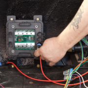
Our customer started at the back of the car. They plugged the long end of the CAN cable into one of the CAN ports on the POWERCELL. Both of these ports are identical so it doesn’t matter which you choose. They ran the cable along the driver’s side of the car up to the MASTERCELL, through a channel under the door sill. They plugged the CAN plug that is in the middle of the cable into the MASTERCELL then ran the short length to the front POWERCELL.
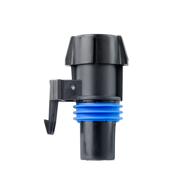
In your kit, there are two accessory plugs that are very important. The both look like this. Please note that the plugs in some kits may be yellow. Others may be cream-colored.
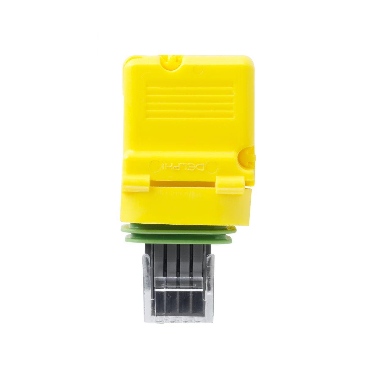
Infinitybox CAN sealing plug
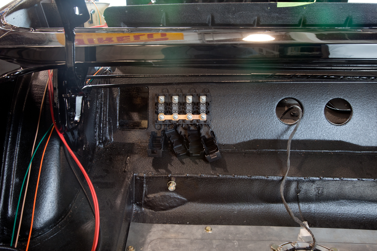
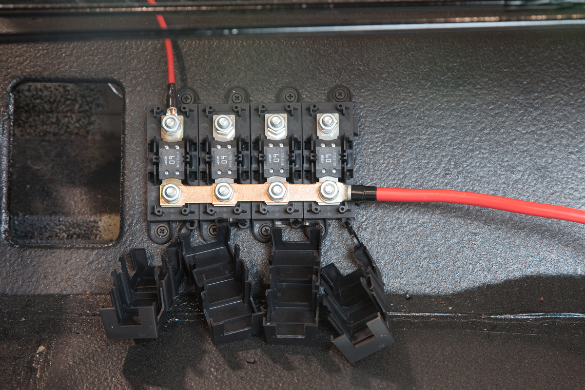
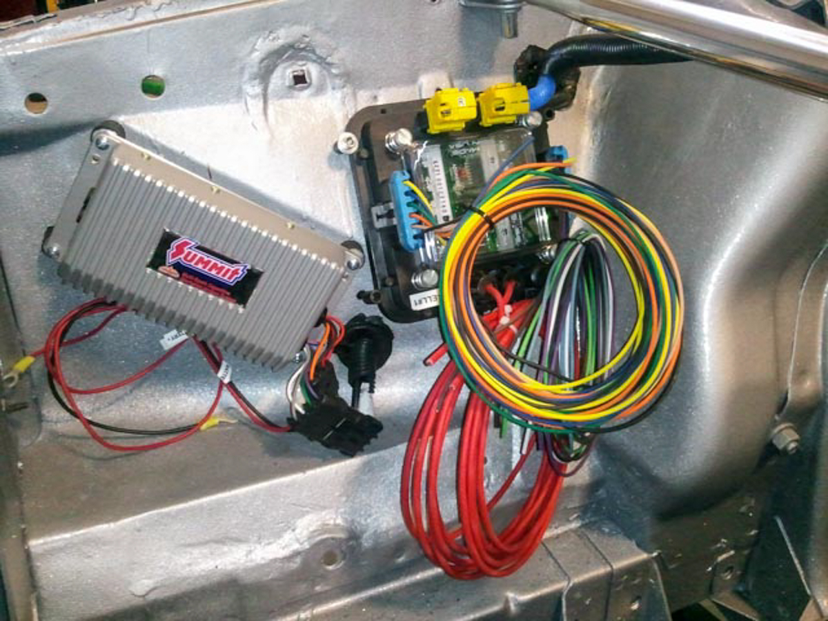
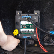
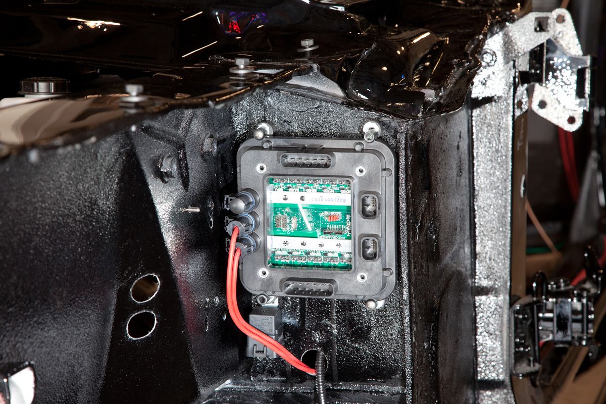
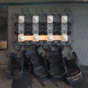
There is a difference between the two plugs. One is just a seal to plug the unused CAN port in your system. This must be installed to keep dirt, debris, moisture and water from entering your cell. The second is a CAN terminator. It is marked with an “R” on the top. This is also a seal to plug up an unused CAN port but it also does something important. There is a resistor in the connector that balances the impedance of the CAN transmission line. This terminating resistor must be plugged in to the cell that is on the longest length of CAN cable from the MASTERCELL. You system will not work correctly without this terminating resistor. In the case of our customer’s 1967 Mustang, the resistor is mounted in the rear POWERCELL. This picture shows the CAN cable connected and the terminating resistor installed.
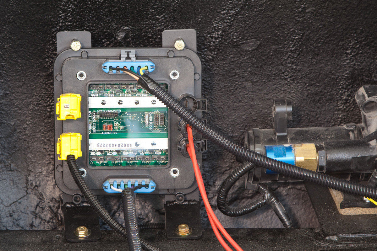
Picture of POWERCELL with CAN cable in 1967 Mustang wired with the Infinitybox system
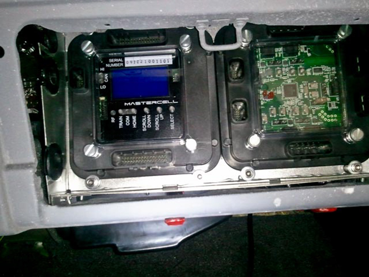
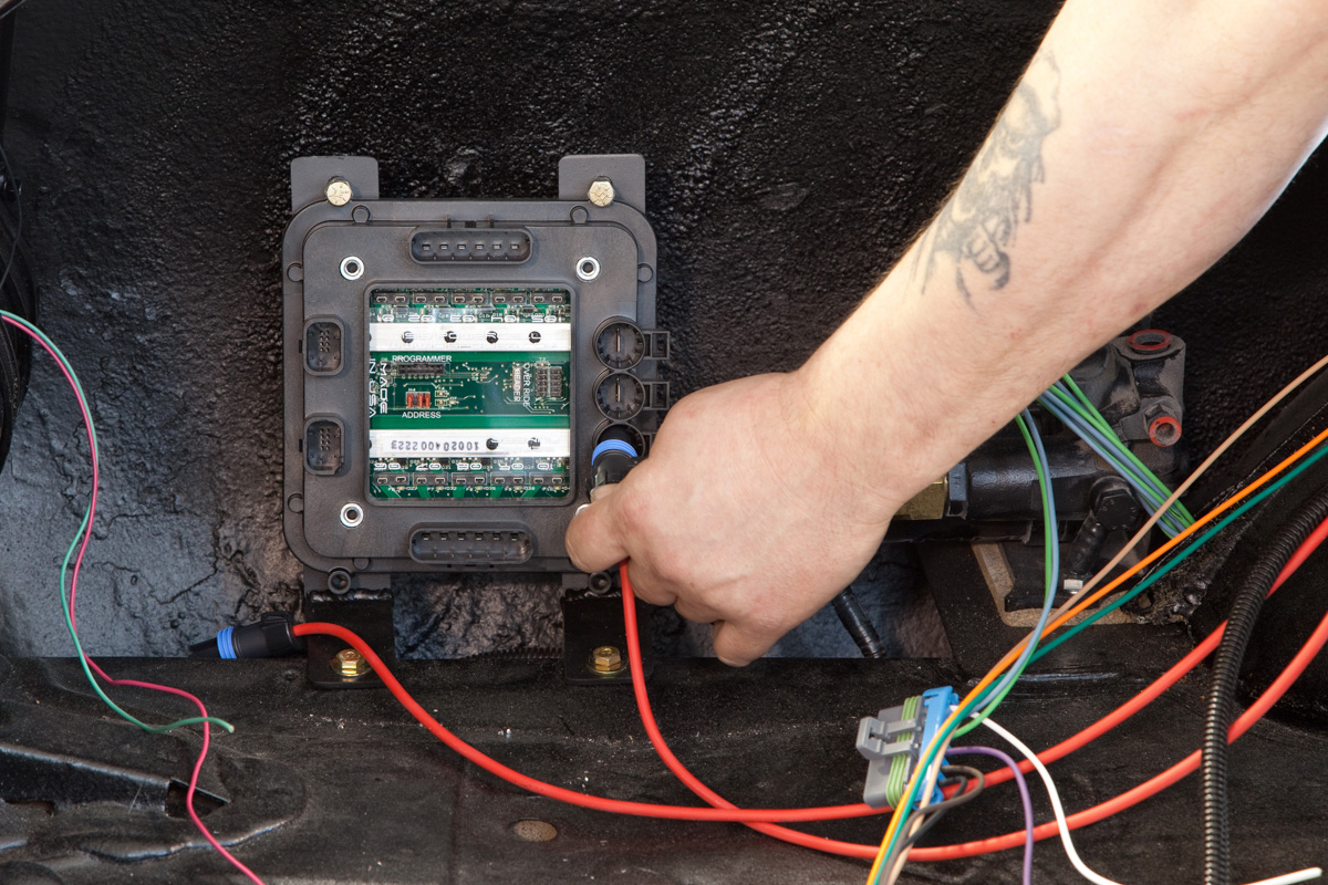
This picture shows the CAN cable connected to the MASTERCELL.
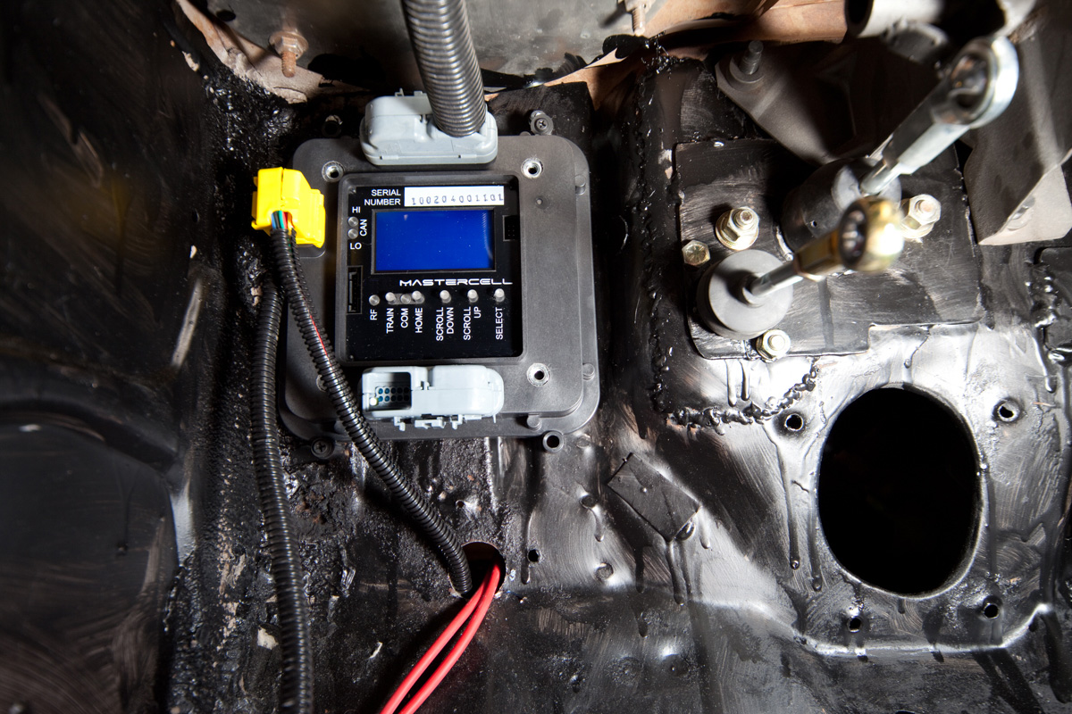
Picture of MASTERCELL installed in 1967 Mustang with CAN cable connected
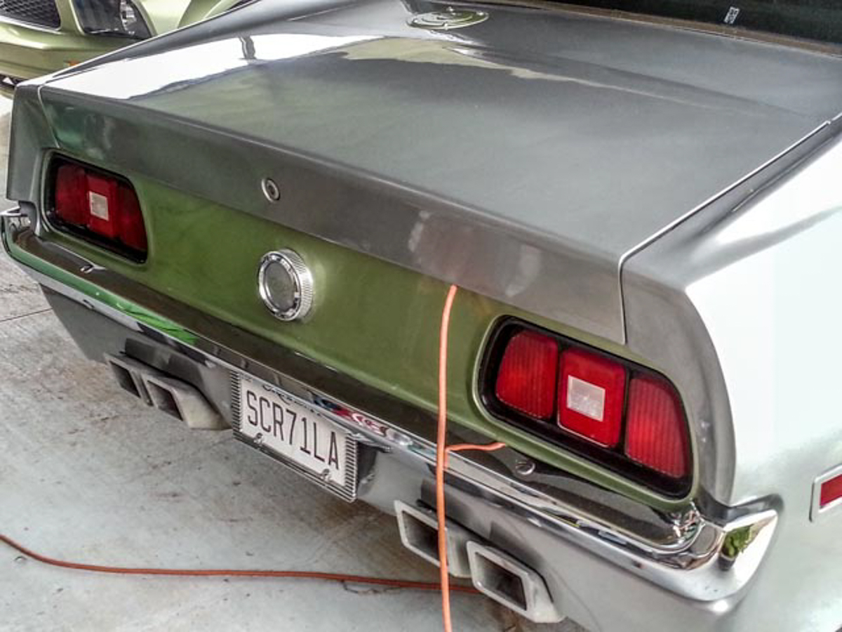
This leads to one of our favorite pictures ever. Take a look at this.
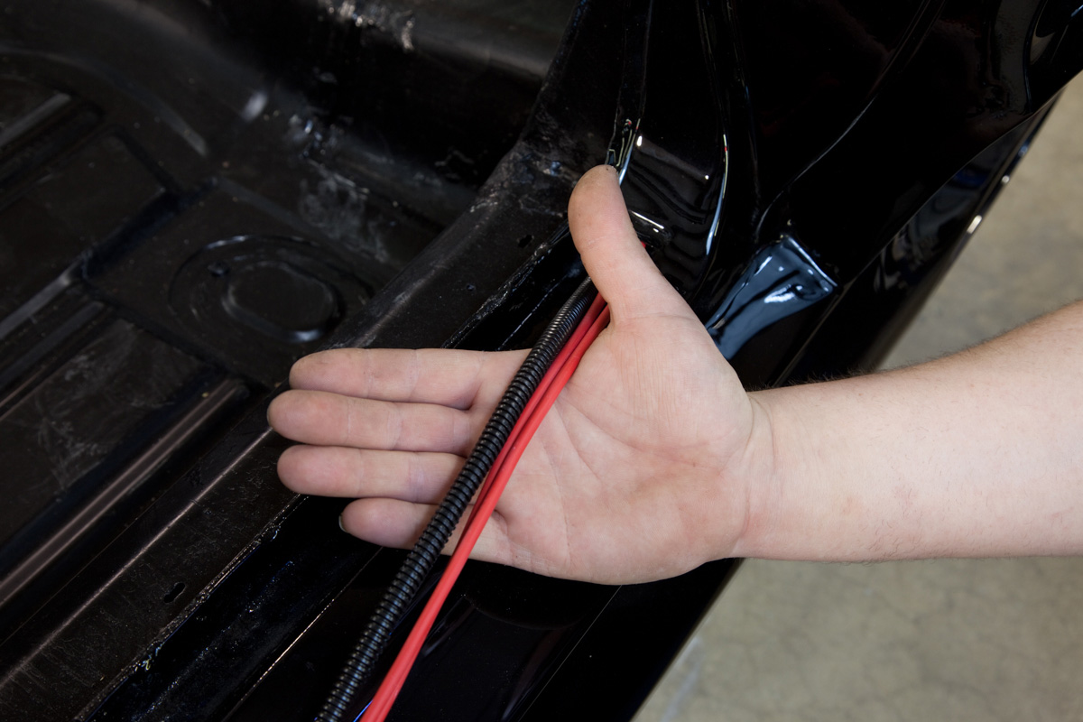
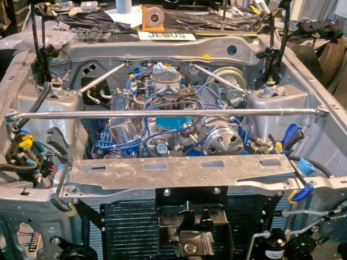
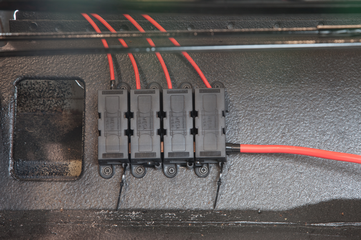
Picture of power and CAN cables running to the back of a 1967 Mustang wired with Infinitybox
This is the entire bundle of wire running from the back of the car to the front. Yes, there is a separate starter cable running from the battery to the starter solenoid and there is fuel wire sender wire bundled in with the CAN cable. Outside of that, the two 8-AWG power cables and the CAN cable are all you need to control everything in the back of the car. This wire is run through the channel under the driver’s door sill.
There are a few more points to hit about the CAN cable.
First, a lot of customers ask if they can lengthen or shorten the CAN cables. Depending on where you mount you cells, you may need different lengths. The answer is “YES”. This link will get you more details on CAN cable lengths. We also get questions about custom, pre-made CAN cables. We also do that. Contact our sales team to discuss details.
Second, there are some considerations that you need to make when you run your CAN cables through the car. The CAN protocol is very noise immune. There are things that we do in hardware and in software to make sure that this is a very reliable signal. That being said, you want to keep your CAN cables (and all of your other electronics in the car) away from the high-voltage coil wires for your ignition system.
Lastly, there is an addendum sheet that comes with any kit that uses the 3-way CAN cable. The CAN cable provides power and ground to the MASTERCELL. Depending on the way your car is assembled, there may be slight differences between the ground potential at the front POWERCELL and the rear POWERCELL. These need to be isolated. You must cut the red and black wires in the one of the lengths of your CAN cable. Click on this link to view this addendum.
Click on this link to contact our team with questions or comments about this post.
 Copyright Infinitybox, LLC 2021. All Rights Reserved.
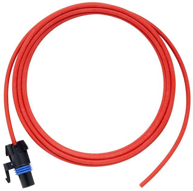
 Copyright Infinitybox, LLC 2021. All Rights Reserved.