 Copyright Infinitybox, LLC 2021. All Rights Reserved.
 Turn Signals with a Trailer Converter
A common question that we get relates to wiring turn signals with our 10-Circuit Kit. A lot of guys want to know if they can wire their cars or trucks with a 10-Circuit Kit instead of a 20-Circuit Kit. We put up a post on our blog a while ago talking about the benefits of one kit over the other. You can read that at this link.
For guys wiring with the 10-Circuit Kit, a lot ask about how to get our 1-filament turn signal feature when there is only one POWERCELL in the system.
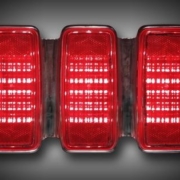
Our standard 20-Circuit Kit gives you several different options for your turn signals in the rear of the car or truck. This link will get you more detail. The option that raises the most questions is what we call 1-filament turn signals. This version uses one filament from a bulb on both sides of the rear of the car to be both the turn signal and the brake light. The easiest way to check for this is by the color of the lenses on your rear turn signals. If they are red, you probably have a one filament configuration. If they are amber, you’d use what we call multi-filament.
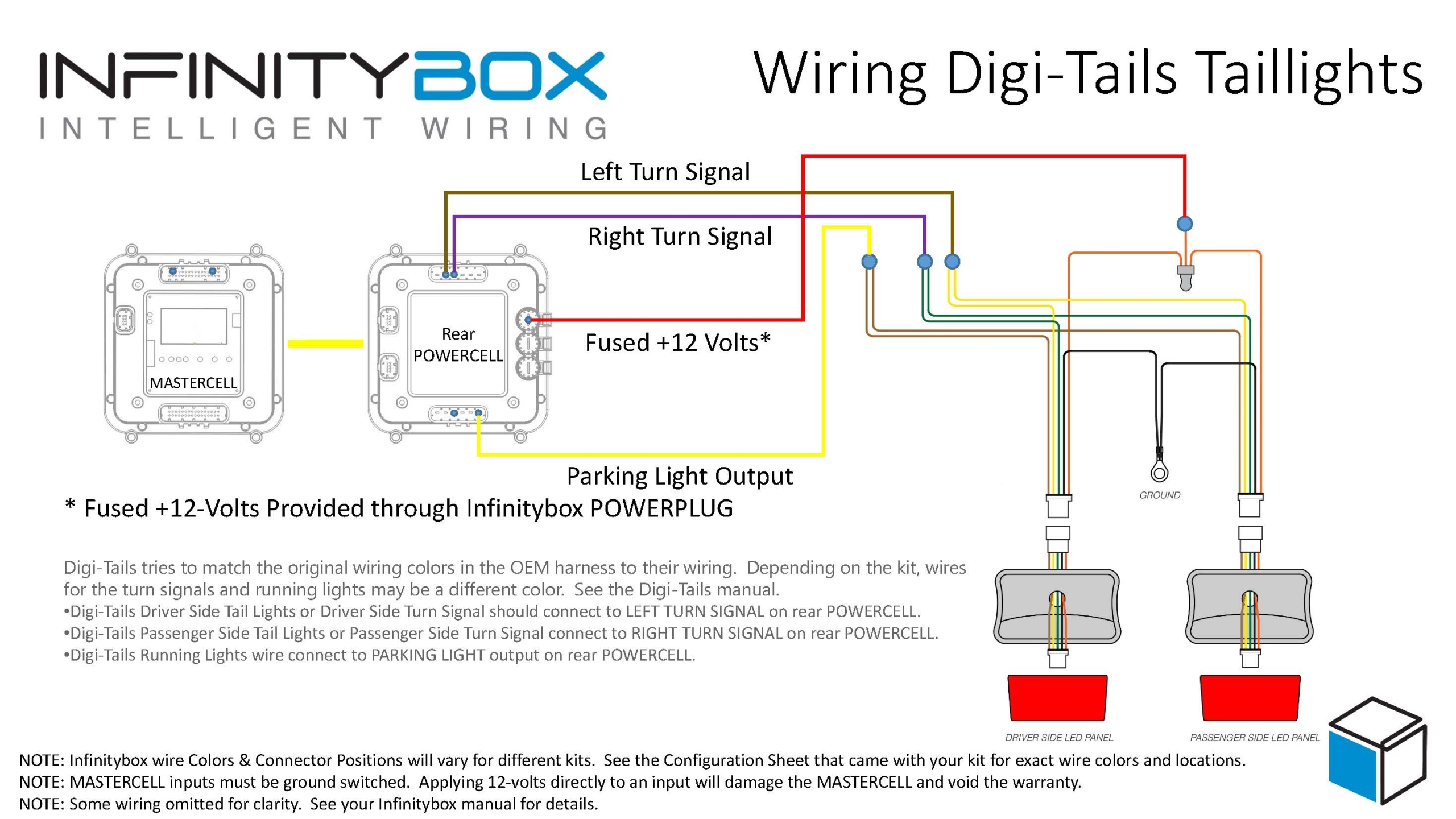
To manage what we call 1-filament turn signals, the POWERCELL turns on both the left and right turn signal outputs at the same time when you step on the brake light. We also have special software in the system that will let one turn signal override the brake light if you have a turn signal on while stopped. With our 20-Circuit Kit, you have two POWERCELLs in the system. The turn signals coming off of the rear POWERCELL act differently than the turn signals on the front POWERCELL.
When you wire your car with our 10-Circuit Kit, you only have one POWERCELL in the system. This means that you have only one pair of outputs controlling your turn signals. You cannot control 1-filament turn signals directly from a single POWERCELL. If you did, your front turn signals would both turn on when you stepped on the brake pedal.
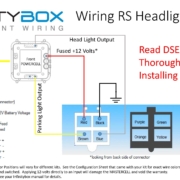
To wire 1-filament turn signals with our 10-Circuit Kit, you need to add a Trailer Light Converter to your wiring harness. These are simple controllers that replicate what we are doing in software for the 1-filament turn signals. This schematic shows you how to wire in a trailer light converter to a 10-Circuit Kit.
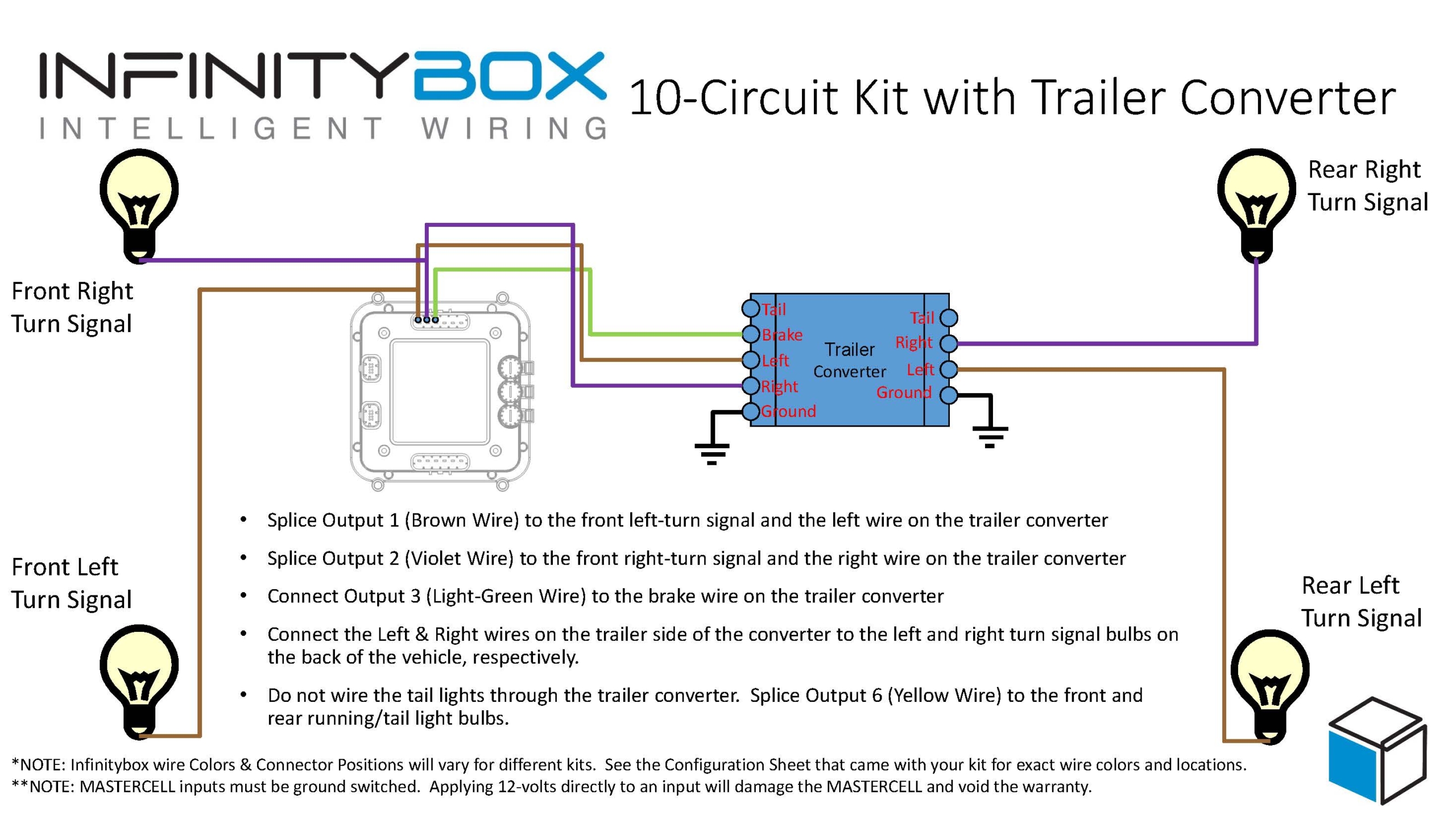
Picture of wiring diagram showing how to use a trailer converter with the Infinitybox 10-Circuit Kit.
There are lots of different companies that make trailer converters. Our customers have recommended these two options.
Contact us if you have any questions about wiring your turn signals. You can download the application note in PDF format by clicking this link.
 Copyright Infinitybox, LLC 2021. All Rights Reserved.

 Copyright Infinitybox, LLC 2021. All Rights Reserved.
  Copyright Infinitybox, LLC 2021. All Rights Reserved.
  Copyright Infinitybox, LLC 2021. All Rights Reserved.
  Copyright Infinitybox, LLC 2021. All Rights Reserved.