Posts

Dakota Digital GSS-3000

This blog post will show you the connections that you need to make between your Infinitybox 20-Circuit Kit and the Dakota Digital GSS-3000 Universal Gear Shift Sender.  The GSS-3000 is designed to drive the gear selector indicators on your dash from any automatic transmission.  Their kit has a rotary potentiometer that connects to the shift linkage on the transmission.  It learns the position of the different gears and sends signals to indicators on your dash to show you what gear you are in.  It is a simple and clever product.  The Dakota Digital GSS-3000 has contacts that are designed to drive your back up lights when you have the transmission in reverse.  It also has a set of contacts for a Neutral Safety Switch.  This sends out a signal when the transmission is in park or neutral and it is safe to start the engine.  Your Infinitybox system can take in these two signals to easily drive your back up lights and manage your Neutral Safety Switch.  Keep reading to learn more.

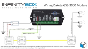
Before you go any further, it is important that you read and carefully understand the instructions for your Dakota Digital GSS-3000 Universal Gear Shift Sender.  You can download these instructions from their website by clicking here.  This blog post is only going to cover the ignition power to the GSS-3000, the neutral safety signal and the connection to the back up lights.  Please follow their instructions for the rest of the wiring to the module.  This picture will show the wiring diagram for the connections to the GSS-3000.

Picture of Infinitybox Wiring Diagram for the Dakota Digital GSS-3000

Picture of Infinitybox Wiring Diagram for the Dakota Digital GSS-3000

First, you need to provide key-on ignition power to the module.  When the key is in the run position, the module will get its power.  You’re going to tap into the ignition output on your front POWERCELL.  Check your configuration sheet for the wire color for your ignition output.  You can splice into this wire directly or you can use one of our Splice Saver Kits to make a simple and clean connection for ignition power.

Next, you can take their Back Up signal and use it to control the back up lights in the back of you car.  The advantage of doing it this way is that you’re running less wire.  The signal will come from the GSS-3000 in the front of the car and connect to the MASTERCELL, also in the front of the car.  The back up lights will get their power from the rear POWERCELL.  You are not running a wire all the way from the GSS-3000 in the front of the car to the back up lights in the rear of the car.  The GSS-3000 puts out a positive signal for the back up lights.  You need to use one of our inVERT Minis to flip this to a ground signal.  See the details in the wiring diagram for how to make these connections.

Lastly, you can use the Dakota Digital GSS-3000 to send the MASTERCELL the signal for the Neutral Safety Switch.  The MASTERCELL needs to see a ground signal through the input for the Neutral Safety Switch.  Check your configuration sheet for specifics on the wire color for your system.  This blog post will get you more details on the Neutral Safety Switch input.  In a lot of transmissions, there is a switch built into them that will give you this signal for when it is safe to start the engine.  If your transmission does not have a built-in safety switch, you can use the signal from the GSS-3000.  This is a ground signal from their SAFETY terminal.  We recommend wiring a 1N4001 diode in series with the MASTERCELL input to isolate the MASTERCELL from the GSS-3000.  This blog post will get you more details about wiring this diode in line.  When you have the transmission in the park or neutral position, the MATERCELL will get the signal that it safe to start the engine.

The is an important consideration here regarding using the GSS-3000 neutral safety signal and the Infinitybox built-in One-Button Start feature.  This feature will not work if you are taking the neutral safety signal from the GSS-3000.  Since the GSS-3000 is getting its power from the ignition output from your POWERCELL, the module will not trigger the neutral safety signal in time for the MASTERCELL to process this.  You will need to use an external neutral safety switch if you want to use our One-Button Start feature and the GSS-3000.

You can download a PDF version of this wiring diagram by clicking this link.

Our technical support team is always available to help you wire your car or truck with our Infinitybox system.  Click this link to contact our team with any questions.


Control module for the Dakota Digital VHX Gauges

Wiring Dakota Digital VHX Gauges

Dakota Digital has been in the business of making advanced electrical products for the Automotive Aftermarket for a long time.  Their products include gauges, lighting, cruise control systems, gear indicators, linear actuators, climate control interfaces and other automotive accessories.  We’ve posted details before on how to wire their cruise control systems and their automatic door lock module.  Their VHX series of gauges has become very popular in the market and a lot of our customers have asked about how to connect their VHX gauge controller box to our Infinitybox system.  This blog post is going to walk you through the details of Wiring Dakota Digital VHX Gauges to our system.

If you are using the RTX gauges, you can click on this link to get to a wiring them.

Before we go too far, this post is only going to cover wiring primary power, ground, key-on power and the signals for the indicators on the dash.  Their manual will cover the details for the rest of the wiring.  Carefully read and understand all of the details of the VHX instructions before you go any further.  You can get their manual by clicking this link.

This diagram shows an overview of the connections to the Infinitybox system for the VHX controller box.

Picture of wiring diagram showing you how to interface your Dakota Digital Gauges with the Infinitybox 20-Circuit Kit

Picture of wiring diagram showing you how to interface your Dakota Digital Gauges with the Infinitybox 20-Circuit Kit

Their VHX controller needs constant power from the battery.  Connect the CONST. POWER terminal on their controller box directly to the positive terminal on the battery.  You must fuse this wire at the battery for safety.  You also have to connect the GROUND terminal on their controller box to a good chassis ground connection.  This must be a metal-to-metal connection that is free of paint, powder coating, dirt and debris.

Here are the connections that are specific to the Infinitybox system.

First, the VHX controller box needs ignition or key-on power.  This is what turns the gauges on when you turn the key in the car.  Your ignition output is going to provide this power.  In most systems, this output is number 3 on the front POWERCELL.  Check the configuration sheet that came with your kit to confirm.  This ignition output is going to power your engine management.  You are going to splice into this wire to connect to the ACC. POWER terminal on the VHX controller box.

Next, you need to connect your parking light output on the front POWERCELL to the DIM(+) terminal on the VHX controller box.  This will turn on the illumination on the VHX gauges when you have your parking or headlights on.  Just like the ignition output, splice into the parking light output on your front POWERCELL and connect this to the DIM(+) terminal.

Lastly, you need to connect the POWERCELL outputs for your turn signals and high-beam to their respective terminals on the VHX control box for the turn signal indicators and high beam indicator.  Just like the key-on power and parking lights, splice into the output wires for the left turn signal, right turn signal and high-beams and connect them to the LEFT(+), RIGHT(+) and HIGH(+) terminals, respectively.  When your POWERCELL is flashing the left turn signal, the indicator for the left turn signal will flash on the Dakota Digital gauges.  When you have your high beams on, your high beam indicator will light up on the gauges.

Our Infinitybox system can power any electrical system in your resto-mod, street rod, pro-touring build or race car.  Wiring Dakota Digital VHX Gauges is a great example of that.  You can download a PDF of this wiring diagram by clicking this link.

Our technical support team is available to answer any questions about blog post or any other topics about wiring your car with our Infinitybox system.  Click on this link to get in touch with our team.


High-Beam Switch

We have the turn-signal switches, horn switch and 4-way switch wired to the IDIDIT steering column in this 1967 wiring project.  Our next step is to wire the high-beam switch.

You have several options to wire your high-beam switch.  The high-beams work just like any other output in the Infinitybox system.  There is a dedicated output on the front POWERCELL that is for the high-beams.  This output gets wired to both of the high-beam bulbs in the front of the car.  The other side of the bulbs connects to ground.

The MASTERCELL connects to the high-beam switch.  When the MASTERCELL input is grounded though the switch, the MASTERCELL sends a command to the front POWERCELL to turn on the high-beams.  Your high-beam switch can be a toggle switch on the dash, a motion on the turn signal stalk or even a push button on the floor.

In the case of this 1967 Mustang install, the customer chose to use our Alternating Headlight Toggle Option that is built into the 20-Circuit Kit.  Here’s how this works.  You connect the Alternating Headlight Toggle input in the MASTERCELL harness to one contact on a momentary button.  You ground the other side of the button.  When you press the button, you connect the MASTERCELL input to ground.

If you press and hold the momentary button with the headlights off, the MASTERCELL will tell the front POWERCELL to turn on the high-beams.  The high-beams will stay on as long as your finger is holding the button.  When you release the button, the high-beams will turn off.  You would use this as your flash-to-pass button.

If you press and release the momentary button with the headlights on, the MASTERCELL will tell the front POWERCELL to toggle between the headlights and high-beams.  It will turn the headlights off then turn the high-beams on.  If you press and release the momentary button again, the MASTERCELL will tell the front POWERCELL to turn the high-beams off and turn on the headlights.  This is a very simple and cool feature.

Our customer chose the Tilt Lever Momentary Switch 510168 option with their steering column.  This gives them a momentary button at the end of the turn-signal stalk.  This is a perfect way to control your high-beams.  Pressing the button with the headlights off gets you flash-to-pass.  Pressing and releasing the button with the headlights on, will control your high-beams.

IDIDIT has some very specific instructions for installing this Tilt Lever Momentary Switch to the column.  You can link to these instructions at this link.  The grey wire going to the momentary switch will connect to the Alternating Headlight Toggle input going to the MASTERCELL.  In our configuration, this is the green-red wire on the MASTERCELL A harness.  That is input 22.  Please refer to your configuration sheet since different configurations may have different wire assignments.

IDIDIT makes some good points in their instructions about grounding the tilt lever.  Be sure to follow their instructions carefully for installing this option.

Please contact us with questions about wiring your high-beam switch to our Infinitybox MASTERCELL.  Click this link to get in contact with a member of our technical support team.

Hazard Lights

We just posted details on how to wire your turn-signal and brake lights to our Infinitybox POWERCELLs.  Here’s a quick follow up to that post.  Once you have your turn-signal outputs wired, wiring your hazard lights is really easy.

Some people call them hazard lights, hazard warning flashers, warning lights, emergency lights, 4-way flashers or simply flashers.  Whatever you call them, these are the flashing lights in the corners of your car that you turn on when you help or when you want to warn other drivers.

In most cars, your hazard lights are simply your turn signals.  The original mechanism in the steering column shunted all of the turn signal bulbs together through the flasher can when you pressed the hazard button.  With our Infinitybox system, you simply turn on an input to the MASTERCELL for the hazard lights.  The MASTERCELL sends a command to the front and rear POWERCELLs to flash the left and right turn signals together.  You do not need a separate flasher can, the POWERCELLs handle that for you.

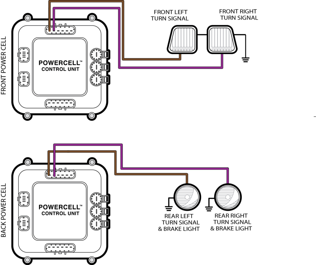
Wiring diagram for 1-filament brake lights and turn signals for the Infinitybox system.

Wiring diagram for 1-filament brake lights and turn signals for the Infinitybox system.

If you look at the line in your configuration sheet for the hazards, you will see that there is a dedicated input going to the MASTERCELL.  You will also notice that the POWERCELL outputs are just the turn signal outputs on the front & rear POWERCELL.  This picture shows the hazard lights details from our standard front-engine configuration.

Configuration details for wiring 4-way flashers with the Infinitybox system

Configuration details for wiring 4-way flashers with the Infinitybox system

If you need it, you can get more information on how to read our configuration sheets by clicking this link.

We’re going to talk about wiring inputs in upcoming posts.  For now, everything that we need to do for the hazard lights in our 1967 Mustang is done since we wired the turn signals.

If you have questions or comments about wiring any parts of your car, truck or commercial vehicle with our Infinitybox system, please click this link to contact our team.

Turn Signals with a Trailer Converter

A common question that we get relates to wiring turn signals with our 10-Circuit Kit.  A lot of guys want to know if they can wire their cars or trucks with a 10-Circuit Kit instead of a 20-Circuit Kit.  We put up a post on our blog a while ago talking about the benefits of one kit over the other.  You can read that at this link.

For guys wiring with the 10-Circuit Kit, a lot ask about how to get our 1-filament turn signal feature when there is only one POWERCELL in the system.

Our standard 20-Circuit Kit gives you several different options for your turn signals in the rear of the car or truck.  This link will get you more detail.  The option that raises the most questions is what we call 1-filament turn signals.  This version uses one filament from a bulb on both sides of the rear of the car to be both the turn signal and the brake light.  The easiest way to check for this is by the color of the lenses on your rear turn signals.  If they are red, you probably have a one filament configuration.  If they are amber, you’d use what we call multi-filament.

To manage what we call 1-filament turn signals, the POWERCELL turns on both the left and right turn signal outputs at the same time when you step on the brake light.  We also have special software in the system that will let one turn signal override the brake light if you have a turn signal on while stopped.  With our 20-Circuit Kit, you have two POWERCELLs in the system.  The turn signals coming off of the rear POWERCELL act differently than the turn signals on the front POWERCELL.

When you wire your car with our 10-Circuit Kit, you only have one POWERCELL in the system.  This means that you have only one pair of outputs controlling your turn signals.  You cannot control 1-filament turn signals directly from a single POWERCELL.  If you did, your front turn signals would both turn on when you stepped on the brake pedal.

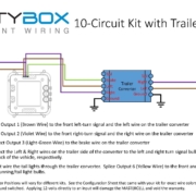
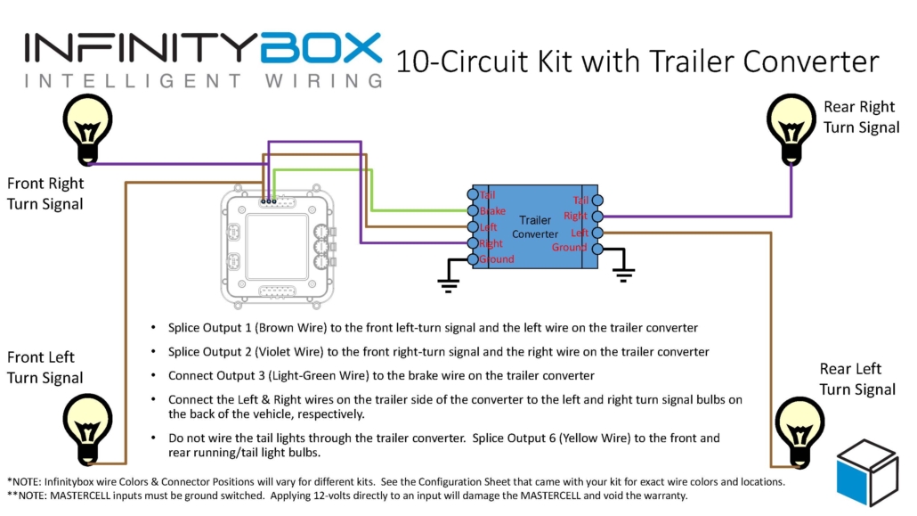
To wire 1-filament turn signals with our 10-Circuit Kit, you need to add a Trailer Light Converter to your wiring harness.  These are simple controllers that replicate what we are doing in software for the 1-filament turn signals.  This schematic shows you how to wire in a trailer light converter to a 10-Circuit Kit.

Picture of wiring diagram showing how to use a trailer converter with the Infinitybox 10-Circuit Kit.

Picture of wiring diagram showing how to use a trailer converter with the Infinitybox 10-Circuit Kit.

There are lots of different companies that make trailer converters.  Our customers have recommended these two options.

Tow Ready 119130

Hopkins 48895

Contact us if you have any questions about wiring your turn signals.  You can download the application note in PDF format by clicking this link.