Posts

Floor dimmer switch

Floor Mounted Dimmer Switch

When it comes to controlling lights with our Infinitybox system, you have many different options.  This is especially true for your headlights and high-beams.  You can see earlier blog posts about wiring headlights and high-beams by clicking these links.  In most cases, you are going to use the headlight and high-beam outputs on the front POWERCELL.  These are controlled by their own inputs connected to different switches on your dash or the steering column.  You can also use a floor-mounted headlight dimmer switch to switch between the headlights and high-beams in your car.  This blog post will show you the details.

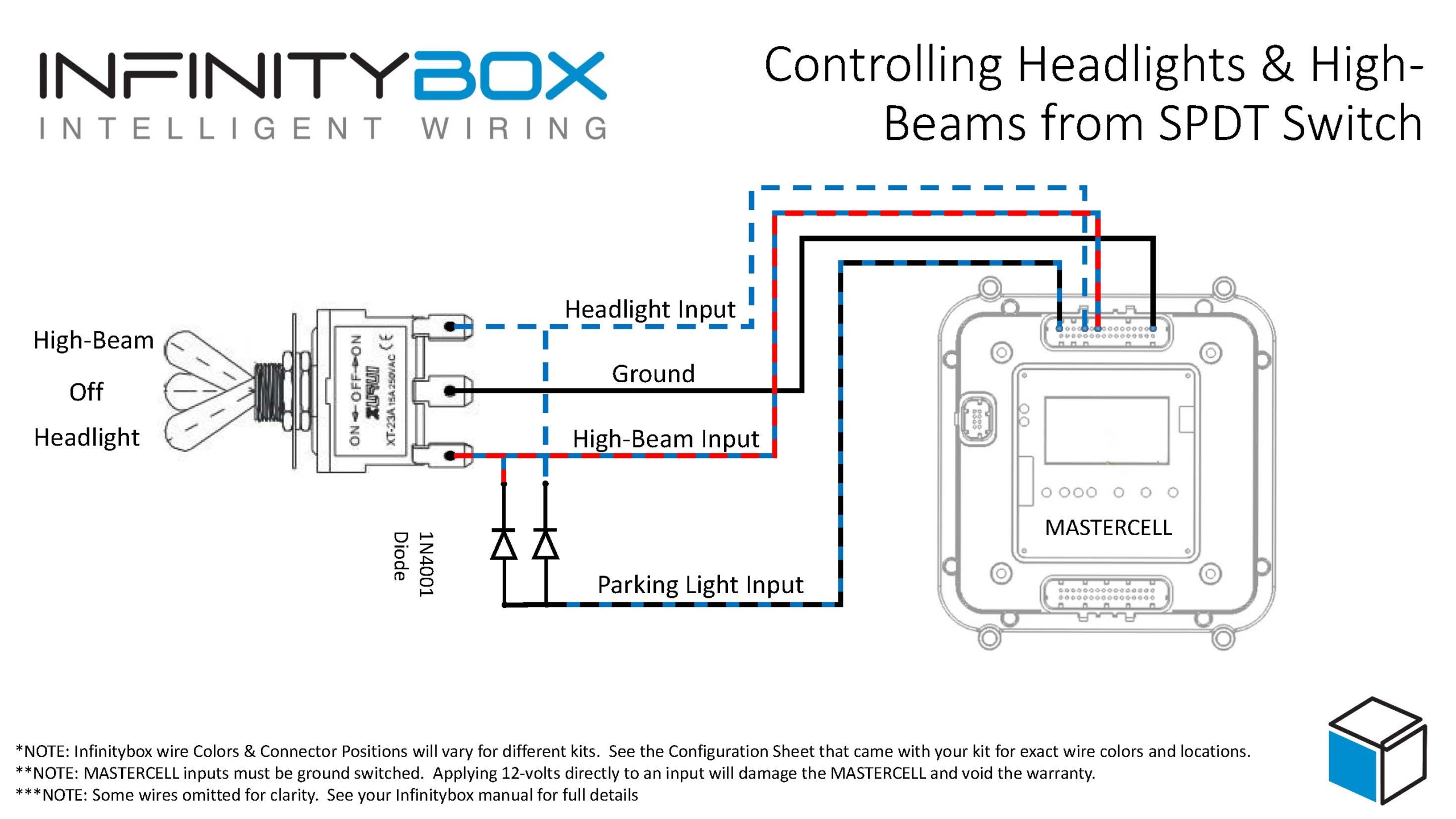
The floor dimmer switch is designed to toggle between the headlights and high-beams.  The headlight switch brought power to a common terminal on the switch.  The headlights and the high-beams wired to their respective output terminals on the switch.  When you turn on the headlight switch, power is applied to the dimmer switch on the floor.  Pressing this switch with your foot toggles between the headlights and high-beams.  When you turn off the headlight switch, there is no power at the switch so your headlights and high-beams turn off.

Floor dimmer switch

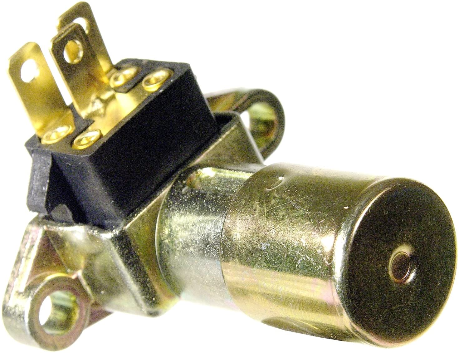
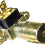
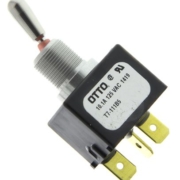
Picture of a floor headlight dimmer switch

Wiring a floor dimmer switch is simple with the Infinitybox system.  First, you are going to wire your headlight switch to the headlight input going to the MASTERCELL.  Remember that the MASTERCELL inputs are ground switched.  When the headlight input is switched to ground, the MASTERCELL will tell the front POWERCELL to turn on the output for the headlights.  We have many different wiring diagrams showing different how to wire different headlight switches in the Resources section of our website.  This link will take you to the wiring details for the most common GM-style headlight switch.

If you are going to use a dimmer switch on floor to switch between headlights and high-beams, you will not need to use the high-beam output on your front POWERCELL.  This opens up this output to be used for other accessories or auxiliary functions.

Next, you are going to connect the headlight output from your front POWERCELL to the common terminal on your dimmer switch.  In most cases, this is the center terminal on the switch.  It may also be labeled as “From Headlight Switch”.  Check the wiring diagram for your specific switch.

Next, you are going to connect the output terminals from your dimmer switch to your headlight bulbs and high-beam bulbs.  The terminals on your switch should be labeled for the headlights and high-beams.  Check the wiring diagram for your specific switch for more details.

Lastly, you can tap off the high-beam terminal on the dimmer switch with a wire for the high-beam indicator on your dash.

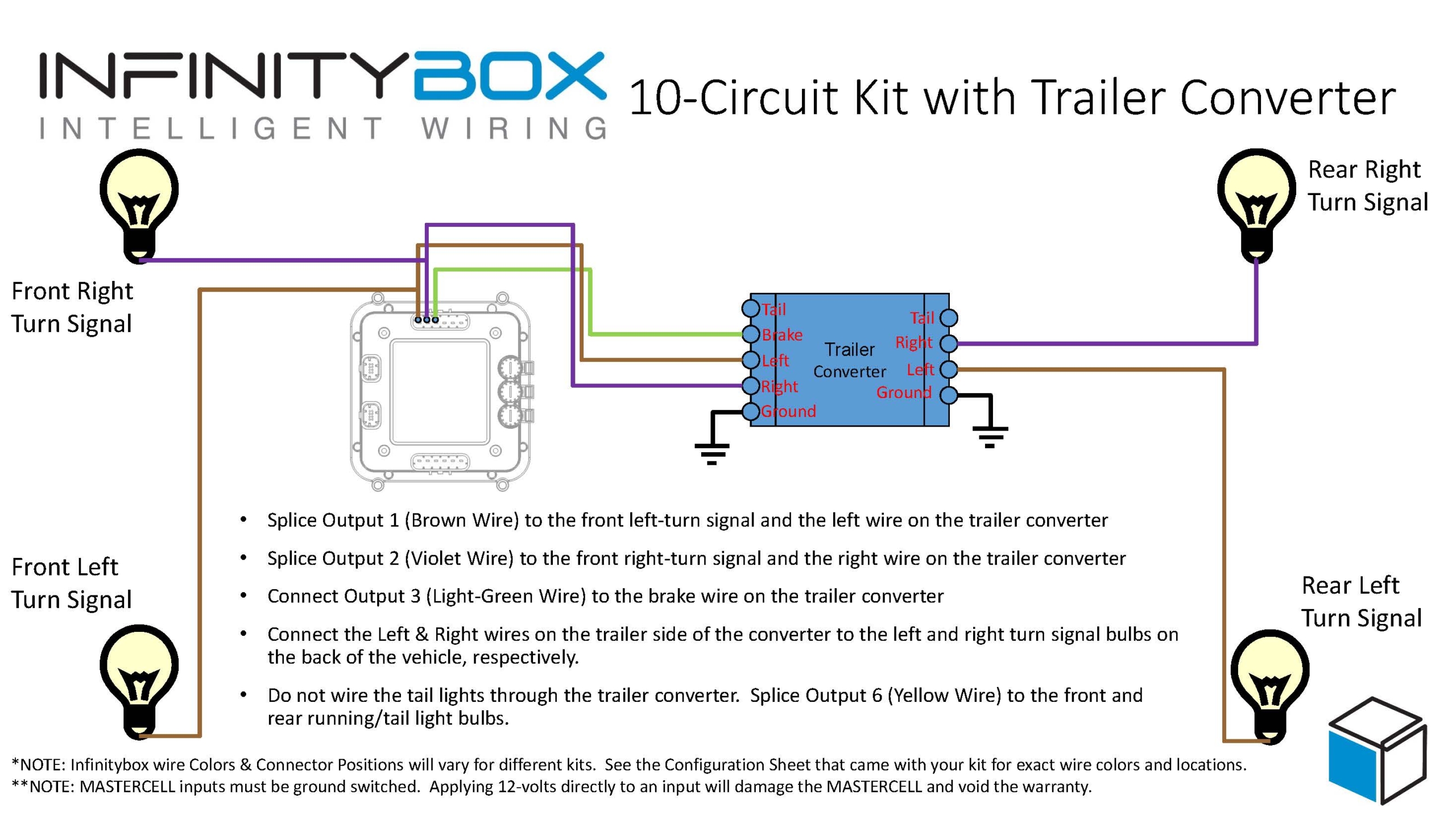
This wiring diagram shows the connection from the MASTERCELL to the headlight switch, the headlight output from the POWERCELL to the dimmer switch, the connections from the dimmer switch to the headlights & high-beams and the connection for the high-beam indicator on the dash.

Floor dimmer switch wiring diagram image

Picture showing wiring diagram for a floor mounted headlight dimmer switch.

You can download a PDF version of this wiring diagram by clicking this link.

Reach out to our team if you have any questions about wiring a floor dimmer switch to control your headlights and high-beams with the Infinitybox system.  You can call us at (847) 232-1991 or click on this link to contact our team directly.

Example of a SPDT Switch

Headlights with SPDT Switch

A customer emailed us to ask how he could control his parking lights, headlights and high-beams from a single switch on his dash.  He wanted to use a toggle switch with three positions: down for head lights, up for high-beams and off in the center.  When either the headlights or high-beams were on, he wants his parking lights on.  This is really easy to do with our Infinitybox system.  Check out the details below to see how easy it is to wire your headlights with a SPDT switch.

There are many different types of toggle switches.  The major categories are sorted into the number of positions or throws of the switch and the number of poles or contacts.  A single throw switch was two positions.  These are designated as single throw or ST.  A three position switch has two throws from the center position: one up and one down.  These are designated as DT for double throw switches.

The number of poles on a switch designates the number of contacts.  The most common is single pole.  This means that each position on the switch is connected back to a common point with a single terminal.  These are designated as SP switches for single pole.  The more complicated switch is double pole.  These have two terminals for each position or throw of the switch.   This link will take you to a good Wikipedia article that talks about switches in more detail.

For this application, our customer needs a SPDT switch.  This is a single pole, double throw switch.  The switch has three positions: off in the center and on in the up and down positions.  It has a single pole for each position.  This diagram will show you how to wire MASTERCELL inputs to control the headlights and high-beams off of this Single Pole, Double Throw Switch.

Picture of a wiring diagram showing how to wire a SPDT switch to control headlights, parking lights and high-beams with the Infinitybox system

Picture of a wiring diagram showing how to wire a SPDT switch to control headlights, parking lights and high-beams with the Infinitybox system

The MASTERCELL input for the headlights connects to the top terminal of the switch.  The input for the high-beams connects to the bottom terminal of the switch.  The middle or common terminal of the switch needs to get connected to ground.  This can go to the chassis or can connect to one of the black ground wires in the MASTERCELL input harness.

When the switch is in the middle position, nothing is connected so the headlights and high-beams are off.  When you flip the switch to the down position, the input for the headlights gets connected to the center terminal, which is ground.  This triggers the headlight input on the MASTERCELL.  To turn on the high-beams, you flip the switch to the up position.

For your parking light input, you need to wire this to both the headlight and high-beam contacts on the switch but there is an important step that you need to follow.  If you were to just wire the parking light input to the headlight and high-beam terminals on the switch, all of the inputs would be electrically connected together.  All three outputs would turn on at the same time in either the headlight or high-beam position.  You need to isolate the headlights and high-beams with diodes for this to work properly.  You need to connect the MASTERCELL input for the parking lights to the headlight and high-beam terminals through two diodes.  These diodes should be a 1N4001 rectifier and these can easily be purchased from Amazon.  The diodes act like one-way check valves.  They do not let the parking light input connect between the headlight and high-beam input.  The orientation of these diodes are very important.  If they are wired backwards, this will not work.  Please look at the wiring diagram for proper orientation of these diodes.

When the switch is flipped to the headlight position, the parking light input gets connected to ground through the diode.  The same thing happens when the switch is in the high-beam position.  The parking lights will turn on when the switch is in the headlight of high-beam position if you follow this wiring diagram.

You can download a PDF copy of this wiring diagram by clicking this link.

If you have questions about this wiring diagram or need specific help wiring your car with our Infinitybox system, click on this link to contact our technical support group.

Turn Signals with a Trailer Converter

A common question that we get relates to wiring turn signals with our 10-Circuit Kit.  A lot of guys want to know if they can wire their cars or trucks with a 10-Circuit Kit instead of a 20-Circuit Kit.  We put up a post on our blog a while ago talking about the benefits of one kit over the other.  You can read that at this link.

For guys wiring with the 10-Circuit Kit, a lot ask about how to get our 1-filament turn signal feature when there is only one POWERCELL in the system.

Our standard 20-Circuit Kit gives you several different options for your turn signals in the rear of the car or truck.  This link will get you more detail.  The option that raises the most questions is what we call 1-filament turn signals.  This version uses one filament from a bulb on both sides of the rear of the car to be both the turn signal and the brake light.  The easiest way to check for this is by the color of the lenses on your rear turn signals.  If they are red, you probably have a one filament configuration.  If they are amber, you’d use what we call multi-filament.

To manage what we call 1-filament turn signals, the POWERCELL turns on both the left and right turn signal outputs at the same time when you step on the brake light.  We also have special software in the system that will let one turn signal override the brake light if you have a turn signal on while stopped.  With our 20-Circuit Kit, you have two POWERCELLs in the system.  The turn signals coming off of the rear POWERCELL act differently than the turn signals on the front POWERCELL.

When you wire your car with our 10-Circuit Kit, you only have one POWERCELL in the system.  This means that you have only one pair of outputs controlling your turn signals.  You cannot control 1-filament turn signals directly from a single POWERCELL.  If you did, your front turn signals would both turn on when you stepped on the brake pedal.

To wire 1-filament turn signals with our 10-Circuit Kit, you need to add a Trailer Light Converter to your wiring harness.  These are simple controllers that replicate what we are doing in software for the 1-filament turn signals.  This schematic shows you how to wire in a trailer light converter to a 10-Circuit Kit.

Picture of wiring diagram showing how to use a trailer converter with the Infinitybox 10-Circuit Kit.

Picture of wiring diagram showing how to use a trailer converter with the Infinitybox 10-Circuit Kit.

There are lots of different companies that make trailer converters.  Our customers have recommended these two options.

Tow Ready 119130

Hopkins 48895

Contact us if you have any questions about wiring your turn signals.  You can download the application note in PDF format by clicking this link.