Programming with the Microchip PICKit 4
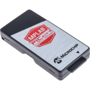
You can use the Microchip PICKit 4 In-Circuit Debugger to load code onto your Infintybox MASTERCELL, POWERCELL and inMOTION cell. This is an advanced feature and you would only need to do this when instructed by the Infinitybox team. There is a special programming harness required. Contact Infinitybox technical support for more details. Please follow these instructions to update your cell with the PICKit 4.
1. You will receive a file to load onto your cell. Save this file to the desktop of your computer.
2. Download Microchip’s MPLAB X IDE software. Click this link to get the latest version of their software. Follow the instructions from Microchip to install the software suite. Once the software is installed, reboot the computer.
3. Plug the PICKit 4 into your computer and let Windows install the drivers. Once the drivers are installed, reboot the computer.
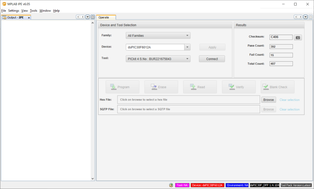
4. Click on your computer’s Start button and go to the Microchip folder under Programs. Launch MPLAB IPE. The application will look like this.
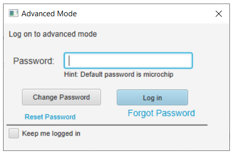
5. Click on the Settings option in the top bar and select Advanced Mode. This will bring up a dialogue box asking for a password. The default password is “microchip”. Type this into the Password field and click on the Log In button. The dialogue box will look like this.
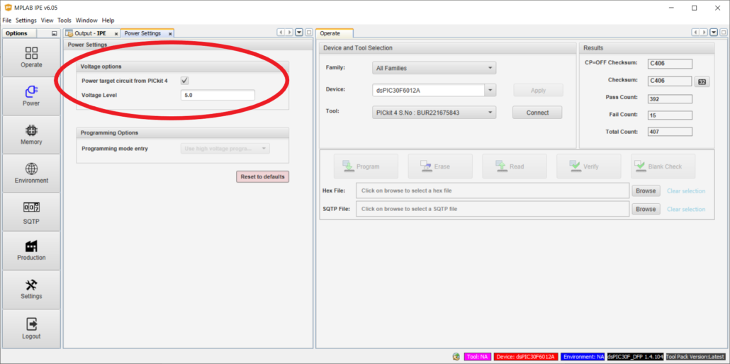
6. The advanced options buttons will appear on the left of your screen. Click on the Power button. This will open a tab with the Power Settings. Click on the box next to “Power target circuit from PICKit 4”. A check should appear in the box as shown in this picture. Make sure that the value in the Voltage Level field is 5.0.
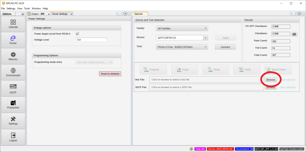
7. Click on the Browse button under the Operate tab as shown in the image below. This will open a dialogue box. Use this box to browse to your desktop to select the file that we emailed you. Select this file and click the Open button. You will get a message in the Output IPE tab that will read Hex File Loaded Successfully.
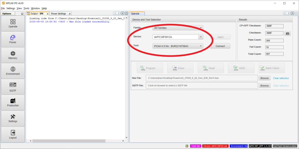
8. Confirm that the Device and Tool are correct. These values are on the Operate tab. The Device should be dsPIC30F6012A. The Tool should be PICKit 4. The following picture shows where these values are located.
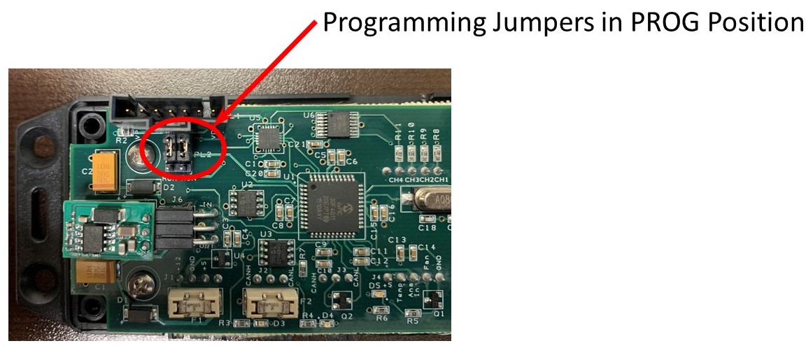
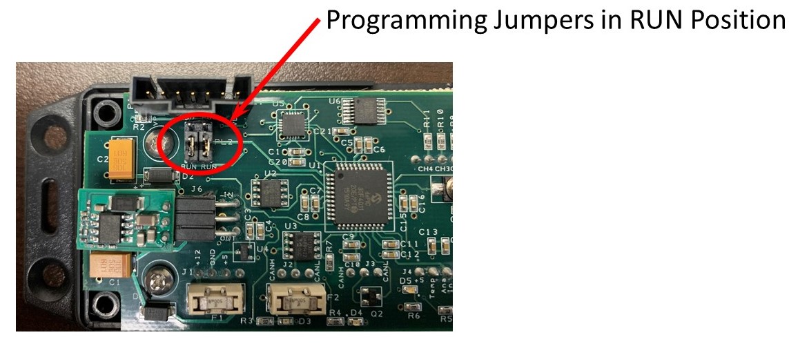
9. Plug the black connector on the PICKit 4 harness into the programming port on the cell to be programmed.
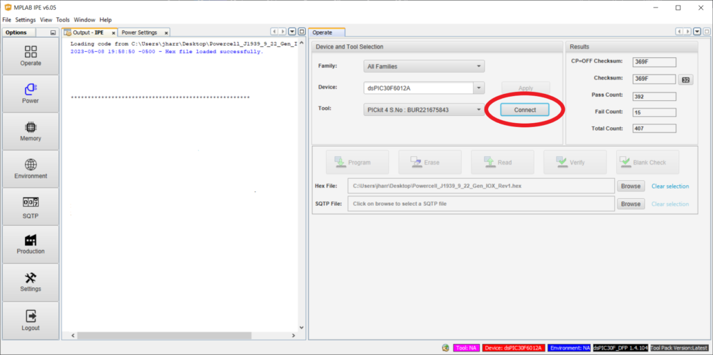
10. Click on the Connect button under the Operate tab. The following picture shows this button.
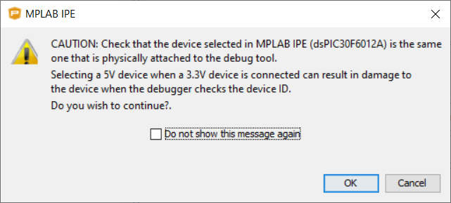
A warning box will appear, as shown below. Click on the OK button to accept this warning.
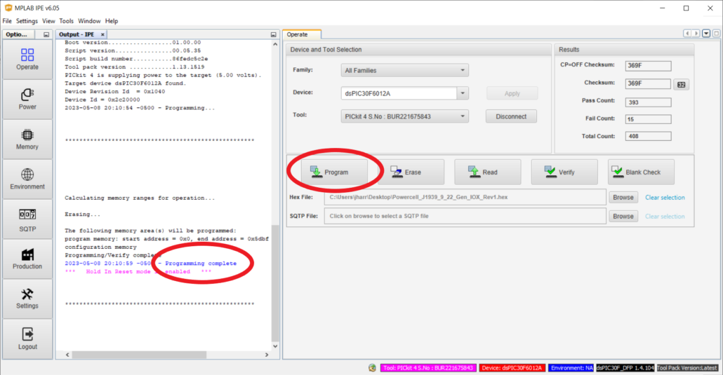
11. Click on the Program button as shown in the picture below. The PICKit 4 will load the hex file into the process of the cell being programmed. This will take 20 to 30 seconds to complete. You will get a message in blue in the Output IPE tab that will say Programming Complete.
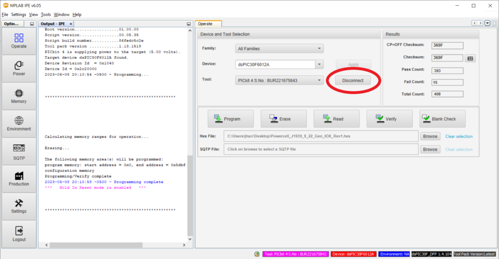
12. Click on the Disconnect button as shown in the picture below and unplug the PICKit 4 from the cell being programmed.
 Copyright Infinitybox, LLC 2021. All Rights Reserved.
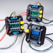 Copyright Infinitybox, LLC 2021. All Rights Reserved.
 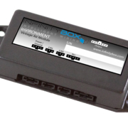 Copyright Infinitybox, LLC 2021. All Rights Reserved.
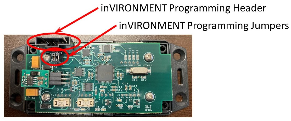

 Copyright Infinitybox, LLC 2021. All Rights Reserved.
  Copyright Infinitybox, LLC 2021. All Rights Reserved.