Race Car Replicas SL-C Steering Column Wiring
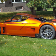
This blog post is going to give you the details for wiring the steering column connector on your Race Car Replicas Superlite Coupe. Fran and his team at RCR have been engineering and manufacturing one of the highest performance and most complete kits to build super cars. Their chassis are engineered to perfection, the body styling is top notch and they give you everything that you need to build you own masterpiece.
They include a General Motors steering column with each kit. This post and wiring diagram are specific to the Oldsmobile column. If you have the older Cadillac steering column with power tilt & telescoping, give our team a call for specifics on the wiring
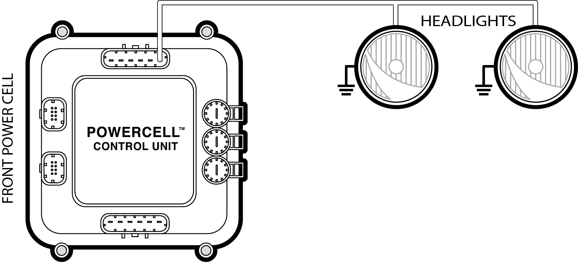
There is a connector on the Oldsmobile column that interfaces with the multi-function turn signal stalk. This has the signals for the parking lights, head lights, high-beams and turn signals. The connections between the steering column connector and the inputs on your MASTERCELL are simple. Here are the details.
First, you need to have a good way to make the connection between our MASTERCELL inputs and the wires going to the steering column. You could cut off the connector on the column and splice these wires together. We recommend a much easier way. You can purchase the mating connector and terminals to make this connection. You can purchase these components from Mouser. These parts are made by Aptiv, formerly Delphi. The part number for the connector is 12092248 and the terminals is 12092345. You will need 9 terminals.
You will need to splice the MASTERCELL input wires for your grounds, turn signals, parking lights, head lights and high beams to these terminals and insert them into the corresponding cavities on the mating connector. The cavity letters are molded into the plastic on the side of the connector. For your grounds, you can use the black ground wires in the MASTERCELL input harness. This list shows you which wire colors correspond to the different mating connector cavities.
Grounds- Black Wire- Cavities D, Q, X & Z
Right Turn Signal- Yellow/Red Wire- Cavity F
Left Turn Signal- Yellow/Black Wire- Cavity G
High-Beam- Blue/Red Wire- Cavity K
Head Light- White/Green Wire- Cavity L
Parking Lights- Blue/Black- Cavity R
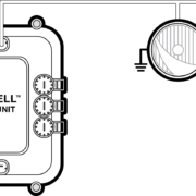
This picture shows the wires from the MASTERCELL and their different cavity locations.
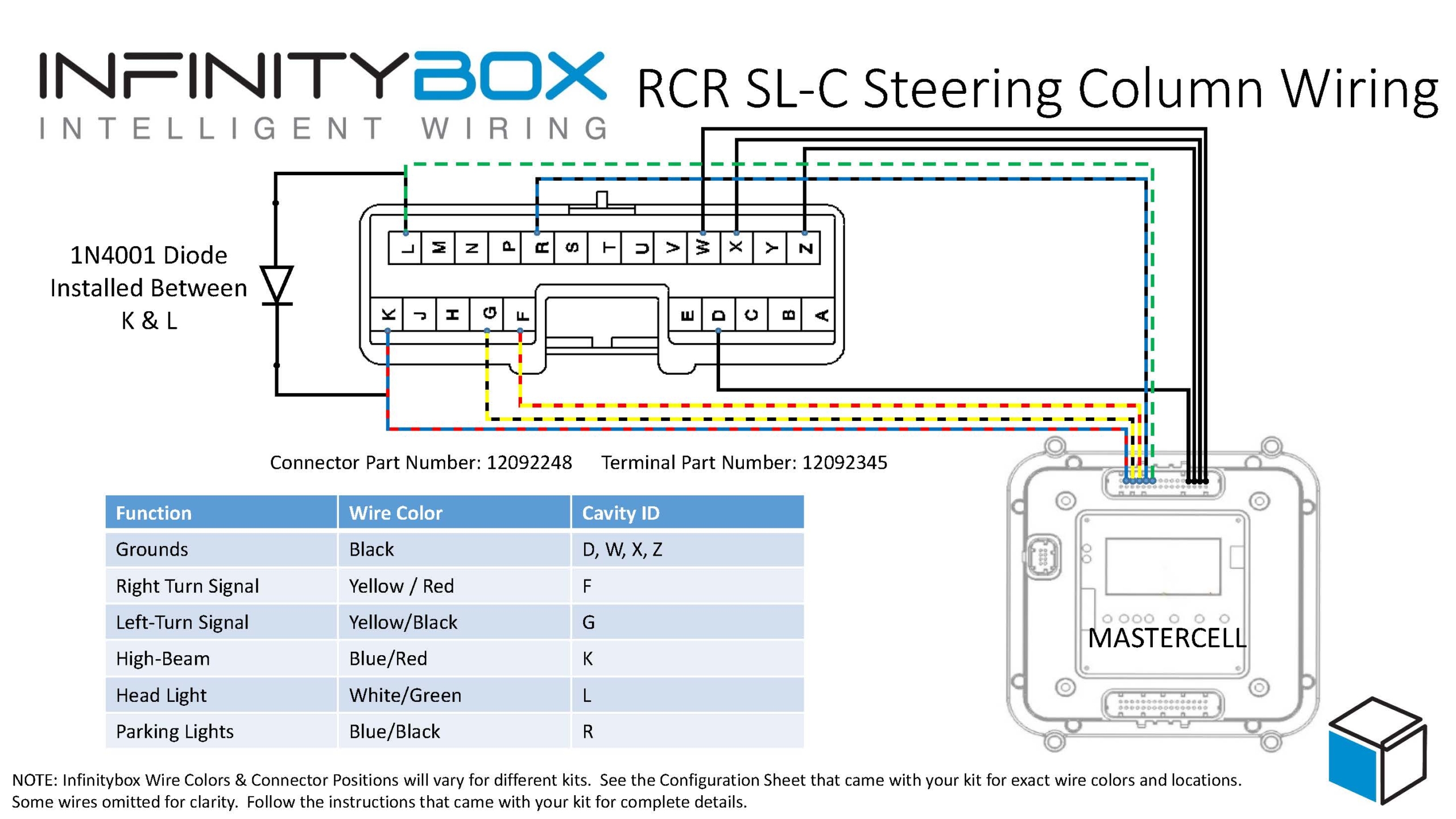
Picture of wiring diagram showing how to connect Infinitybox MASTERCELL inputs to steering column connector for Race Car Replicas SL-C
It is also important that you install a diode between the inputs for the head lights and high-beams. This should be a 1N4001 diode which can be purchased from Amazon or any other on-line electronics store. The orientation of this diode is very important. The cathode or the stripe on the diode must be connected to the high-beam input going to the MASTERCELL. This is the blue/red wire going into cavity K. You can crimp the leads of this diode to the terminals with the MASTERCELL wires to make this easier.
That is all you need to know to connect your MASTERCELL input wires to your steering column connector for your Race Car Replicas SL-C. You can download a PDF version of this wiring diagram by clicking this link. If you have any questions, you can call our team directly at (847) 232-1991 or click here to contact us directly.
 Copyright Infinitybox, LLC 2021. All Rights Reserved.