 Copyright Infinitybox, LLC 2021. All Rights Reserved.
 LS3
GM created something amazing when they introduced their E-Rod crate engine package. You get the same LS3 powerplant found in the new Camaro and Corvette. You can drop that into anything that you’re building and get an emissions compliant engine package.
When you buy the E-Rod, you get the option to buy the engine harness for the LS3 direct from GM. Alternately, you can go with ECUs and engine harnesses from many other manufacturers. This post is going to talk about how you connect your GM LS3 engine harness to your Infinitybox 10 or 20-Circuit wiring harnesses.
Before you go anywhere, you must thoroughly read and understand the literature that came from General Motors about your LS3 engine and the wiring harness. This link will take you to the engine control harness literature from GM.
Another important note, this post is only going to talk about connecting the engine harness to the Infinitybox system. This is going to include the main battery power, the ignition power, the fuel pump trigger and the cooling fan trigger. Read the GM literature for all of the other electrical connections to the engine.
The first connection that must be made is the primary battery power to the fuse box in the engine harness. GM recommends an 8-AWG cable running directly from the battery to the main battery connection on the fuse box. This is a bolted connection on the side of the box. See the GM literature for proper fusing of this power feed.
There are three ground connections that must be made on the engine harness. See the GM literature for more specifics on properly connecting these grounds.
Next, you need to connect ignition power from your POWERCELL to the engine harness. See the configuration sheet that came with your Infinitybox system for the correct wire color for your ignition output. This will connect to the pink wire in the engine harness. When your MASTERCELL input for the ignition is triggered, you will have battery power on the POWERCELL output, which will power the ECU.
Next, you need to connect the fuel pump output from the engine harness to your MASTERCELL input. The GM engine harness puts out a 12-volt signal for the fuel pump trigger. This must inverted to a ground signal to properly connect to the MASTERCELL. You can use one of our inVERT Minis to invert this signal. This link will take you to more information on the inVERT Mini. You can also use a relay to invert this signal. Different versions of the LS3 engine harness have different colors for the fuel pump wire. See the GM literature that came with your engine for more details.
Lastly, you need to connect the cooling fan output from the engine harness to your MASTERCELL input. Just like the fuel pump, the GM engine harness puts out a 12-volt signal for the cooling fan. Follow the instructions for the fuel pump to properly invert this signal to the MASTERCELL. Just like the fuel pump, different versions of the LS3 engine harness have different colors for the cooling fan wire. See the GM literature that came with your engine for more details.
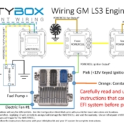
This diagram shows the details of the connections between your Infinitybox system and the LS3 engine harness.

Image of Infinitybox diagram showing how to wire the General Motors LS3 ECU with the 20-Circuit Kit
You can download a PDF version of this wiring diagram by clicking this link.
Here’s how the whole thing works. When you turn on your ignition, the MASTERCELL tells the POWERCELL to turn on the ignition output. This powers up the engine harness and the ECU. The ECU will send a signal to the MASTERCELL when it wants the fuel pump to run. The MASTERCELL will send a signal to the POWERCELL in the rear of the car to provide power to the fuel pump. When the engine is running, the ECU will send a signal to the MASTERCELL when it is at temperature and the cooling fan should turn on. The MASTERCELL sends a command to the front POWERCELL to power the fan. When the engine temperature drops below the set point in the ECU, it will turn off the input to the MASTERCELL. The MASTERCELL will send a command to the POWERCELL to turn off the cooling fans.