Posts

Wiring the Holley HP EFI System

This blog post goes through the details of wiring the Holley HP EFI System with our Infinitybox 20-Circuit Kit.  We will show you the ease and simplicity of wiring your EFI system with Infinitybox.  The wiring is simple and short and you can eliminate the need for external relays.  We’ll go through the key steps and give you a wiring diagram that shows you all the details to wire your Holley HP EFI Engine Management System with our Infinitybox system.

Before we get too far, you must thoroughly read and understand the instructions that came from Holley to install the HP EFI system.  Please consult their website to get the instillation instructions.  The other important thing to consider here is that we are going to show you how to connect your Infinitybox wiring system to the Holley HP.  This will include wiring the key-on ignition power, the cooling fan trigger and the fuel pump trigger.  Consult the Holley manual for all details regarding primary power from the battery, coil wiring, injector wiring, sensor wiring and grounds.  This diagram shows you the connections between your Infinitybox system and the Holley HP ECU.

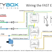
Picture of wiring diagram showing how to wire Holley HP EFI system with the Infinitybox wiring system

Picture of wiring diagram showing how to wire Holley HP EFI system with the Infinitybox wiring system

Your Infinitybox 20-Circuit Kit powers the key electrical systems in your car.  We’re going to provide the key-on ignition power to the Holley HP system.  You are going to connect your POWERCELL ignition output to the 12V Switched wire in the Holley Harness.  This is their Red/White wire.  In most Infinitybox configurations, your ignition output is the light-green wire on your front POWERCELL but we encourage you to always use your configuration sheet to confirm wire colors in your specific kit.  You can get more details on your configuration sheet by clicking this link.  When you turn on your ignition switch, the POWERCELL will provide the key-on ignition power that the Holley HP needs to run.  You can learn more about wiring your ignition switch to your MASTERCELL by clicking this link.

You can use an output your Infinitybox rear POWERCELL to provide the power to your fuel pump.  There are several advantages to using the fuel pump output on your POWERCELL.  First, you do not need to use a relay.  The POWERCELL has the capability to control 25-amps to your fuel pump directly without a relay.  The second advantage is that you can power the fuel pump from the POWERCELL in the back of your car.  This keeps your wiring short and easy to install.  The Holley HP ECU has a fuel pump trigger that you can connect into the MASTERCELL input for your fuel pump.  The Holley fuel pump signal is +12 volts so you must use one of our inVERT Minis to flip this to a ground trigger to go into the MASTERCELL.  You can learn more about the inVERT Mini at this link.

You can also use an output on your Infinitybox front POWERCELL to power your cooling fan.  You get same benefits with your cooling fan as you do your fuel pump.  Your wiring is shorter and you do not need to use an external relay to control the fan.  You can either use a thermostatic switch on the engine or you can have the Holley HP ECU send the MASTERCELL the signal to control the fan.  This link will show you how wire in a thermostatic switch.  The Holley HP ECU has programmable outputs that can be used to signal the MASTERCELL input for the cooling fan.  You need to use one of their “G” or ground switched outputs and need to configure this within their software tool.  You must use a diode to isolate the output on the Holley HP from the MASTERCELL.  See the details in our wiring diagram.

Those are all of the connections that you need to make between your Infinitybox 20-Circuit Kit and the Holley HP EFI system.  You can download a PDF of this wiring diagram by clicking this link.

Click on this link to contact our technical support team if you have any questions about wiring your Holley HP EFI system with Infinitybox.

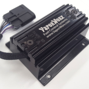
Picture of the VaporWorx Fuel Pump PWM Controller

Wiring VaporWorx Fuel Pump Controller

We always say that our Infinitybox system plays nicely with other electrical accessories in your car.  This blog post is another great example of that.  We got a call from a customer asking about wiring the VaporWorx Fuel Pump Controller with his Infinitybox 20-Circuit Kit.  He was worried about having to wire in additional relays and run a lot of wire.  In reality, wiring the VaporWorx Fuel Pump Controller is simple and easy with the Infinitybox system.

The VaporWorx guys make some very cool products.  Click here to get to their website.  You have to appreciate a company with the tagline “We Give You Gas”.  Their core products improve the delivery of fuel in your resto-mod, street rod, hot-rod or Pro-Touring build.  They have been innovating products for reliable fuel delivery in cars with EFI systems since 2009.

Their core products are designed for returnless fuel systems.  There is only one fuel line going from the in-tank pump to your fuel rail.  There is no fuel regulator on the rail and no return line that brings excess fuel back to the tank.  Their Fuel Pump Controller mounts in the rear of the car, near the fuel pump.  It actively monitors the fuel pressure in the line at the outlet of the pump.  Using pulse-width modulation (PWM), they vary the pump power to keep the fuel pressure within a tight window.  This reduces dead-heading of the fuel pump and also reduces the amount that the fuel gets heated.  We use PWM to control things like fan speed and light dimming from our POWERCELLs and have blogged about how that works before.  Click on this link to learn more about PWM.

This blog post is going to walk you through wiring the VaporWorx fuel pump controller with our Infinitybox system.  We are only going to cover the connections from the battery, from the POWERCELL and to ground.  See their manual for more details on the rest of the sensor wiring required for their controller.  You can access the manuals and installation instructions for their products by clicking this link.

Just like any other blog post where we talk about integrating the Infinitybox system with other products, please carefully read and understand all of the steps required to install the VaporWorx Fuel Pump Controller.  You are messing with flammable fuel and electricity.  Make sure you are completely comfortable with doing this job.

For the sake of this blog post, there are three connections that we are going to cover: primary power from the battery, the fuel pump trigger from the POWERCELL and the grounds.

The primary power for the fuel pump controller is going to come directly from the battery.  This should be a simple connection since the controller should be mounted close to the pump in the tank and most guys are relocating their batteries to their trunks.  Follow the recommendations from VaporWorx for the gauge of wire going from the positive terminal on the battery to the BAT+ terminal on their module.  It is very important that this gauge of wire is sized correctly and that it is fused as close to the battery as possible.

Next, the fuel pump controller and the fuel pump need to be grounded.  The VaporWorx team recommends that you ground their pump controller and the fuel pump directly to the negative terminal of the battery.  This should be easy in most installs since guys are relocating the batteries to their trunks.

Last, the VaporWorx controller needs a fuel pump enable signal from the ECU.  When wired with the Infinitybox system, this signal is going to come from the fuel pump output on your rear POWERCELL.  In most 20-Circuit Kits, this is the TAN wire on the rear POWERCELL but check your configuration sheet for details on this output.  The POWERCELL output is going to connect to the blue wire in the GT150 connector.

The advantage of using the POWERCELL to supply the fuel pump enable signal is that you do not need to add any additional wiring.  You already have the POWERCELL located in the rear of your car.  You do not need to run a wire from the front of the car to the back.  You can simply use the POWERCELL to supply this signal.

Once you have power, ground and the fuel pump enable signal wired, you need to wire your EFI system to your Infinitybox MASTERCELL.  This is how the POWERCELL knows when to turn on the output for the fuel pump enable signal.  To do this properly, you need to understand if your EFI system uses a ground trigger for the fuel pump or a positive signal for the fuel pump.  The wiring diagram for your EFI system will define this.  Alternately, we have wiring diagrams for all of the popular EFI systems in the Resources section of our website.

If your EFI system sends a ground trigger for the fuel pump enable signal, you can wire the MASTERCELL fuel pump input to the EFI system’s fuel pump output.  We strongly recommend wiring a diode in series to buffer the MASTERCELL from the ECU.  As an example, the FAST XFI 2.0 sends a ground trigger for the fuel pump enable signal.  You can see how the recommended diode is wired at this link.

If your EFI system sends a positive trigger for the fuel pump enable signal, you need to flip this to a ground trigger.  You can use one of our inVERT Mini Buffers to do this easily.  The Holley Sniper EFI System uses a positive trigger for the fuel pump enable signal.  You can see how to wire in the inVERT Mini at this link.

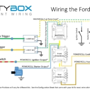
This wiring diagram shows you all of the connections between our Infinitybox system and the VaporWorx Fuel Pump Controller.  You can download a PDF version of it by clicking this link.

Picture of the Infinitybox wiring diagram showing how to wire the VaporWorx Fuel Pump PWM controller with the Infinitybox system

Picture of the Infinitybox wiring diagram showing how to wire the VaporWorx Fuel Pump PWM controller with the Infinitybox system

Please note that some wires are omitted from our diagrams to make them more clear.  Carefully follow the instructions that came with your Infinitybox system and the VaporWorx module for the full instructions.  Also note that the MASTERCELL input and POWERCELL output wire colors may vary depending on your specific kit and the options you have.  Always follow the configuration sheet that came with your kit.

Click on this link to contact our technical support team with any questions about wiring your VaporWorx Fuel Pump Controller with our Infinitybox system.

Fuel Pump Trigger

Let’s talk about fuel pump triggers.  In a previous post, we talked about wiring the fuel pump to the POWERCELL output.  In this post, we’re going to talk about how to connect the MASTERCELL input to the fuel pump trigger. We’re getting towards the end of our customer’s install of our 20-Circuit Kit into their 1967 Mustang.  In previous posts, we’ve shown how to mount the MASTERCELL, POWERCELL and primary fuses.  We’ve shown how to run the primary power cables and the CAN cable that connects the cells together.  We’ve gone step-by-step through the process of connecting the POWERCELL outputs to the lights, fans, ECU, starter solenoid, fuel pump and other switched loads.  We’ve shown how to connect your MASTERCELL inputs to the different switches in the car.

It’s time to wire the fuel pump trigger.   Remember how the Infinitybox system works, your loads (lights, fans, pumps, ECU, starter solenoid and other switched functions) get their switched power from the POWERCELLs.  You place the POWERCELLs locally in the car where  you need them.  You connect your switches to the MASTERCELL, which is usually under the dash.  The MASTERCELL connects to the POWERCELLs through a thin data cable.  When you turn on a switch, the MASTERCELL sends a command to one of the POWERCELLs to turn on an output.

In the case of the fuel pump, there is a dedicated output on the rear POWERCELL.  In the case of this 1967 Mustang Kit, this is the tan wire on the POWERCELL A output harness.  That is output 10.  The input wire to the MASTERCELL is number 19.  This is the tan wire with the yellow tracer wire on the MASTERCELL B input harness.  Check your configuration sheet for the specifics on the POWERCELL output wire and the MASTERCELL input wire.

When you ground the MASTERCELL input wire for the fuel pump, the MASTERCELL sends a command to the rear POWERCELL to turn on 12-volts on output 10.  This provides the switched battery power to the fuel pump.  When you disconnect the MASTERCELL input wire from ground, the POWERCELL turns off the output for the fuel pump.

Our customers have many different ways that they want to control their fuel pump.  The easiest is to trigger it with the ignition switch.  To do this, simply connect the fuel pump input wire to the ignition terminal on the key switch.  This wire is would be wired to the same terminal as the MASTERCELL input for ignition.  When the key is in the run position, the inputs for both the ignition and fuel pump would be connected to ground.  The MASTERCELL would tell the front POWERCELL to turn on the ignition output and tell the rear POWERCELL to turn on the fuel pump output.

Another way to do this is to have a separate switch for the fuel pump.  Most race cars have this.  A lot of guys will wire their cars this way because it is easier to work on the car plus it gets you an extra level of security.  Unless you know to flip the fuel pump switch, the car won’t start.  You’d wire a separate fuel pump switch no differently than any other switch to the MASTERCELL.  The MASTERCELL input wire would connect to a normally open terminal on the switch.  The other side of the switch would connect to ground.  Turning on the switch connects the MASTERCELL input to ground, which turns on the fuel pump output on the rear POWERCELL.

Another option for controlling your fuel pump is to connect the MASTERCELL input to your ECU.  Most engine management and EFI systems have an output that triggers the fuel pump.  You can connect this wire from the EFI system to the MASTERCELL to have the ECU tell the Infinitybox system when the pump should be on or off.

There is an important warning that you must watch here.  Remember that the MASTERCELL inputs are designed to be connected to ground.  Applying battery voltage to the inputs may damage them and void the warranty.  Carefully read the manual that came with your EFI system to understand how their fuel pump trigger is set up.  They will usually be identified as either a positive or negative trigger.

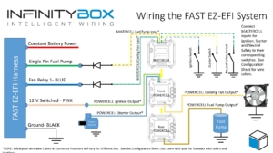
If the fuel pump trigger is negative, you can connect that to the MASTERCELL input wire.  We strongly recommend soldering a 1N4001 diode in between the MASTERCELL input wire and the EFI system trigger wire for the fuel pump.  This isolates the MASTERCELL from the EFI system.  Diodes are directional parts so you must wire them with the cathode side facing towards the ECU.  That is the side of the diode that has the stripe on it.  This picture shows an example of the FAST EZ-EFI system and how to wire the diode into the fuel pump trigger.

Picture of wiring diagram showing how to wire the FAST EZ-EFI fuel injection system with the Infinitybox system.

Picture of wiring diagram showing how to wire the FAST EZ-EFI fuel injection system with the Infinitybox system.

If your EFI system has a positive trigger for the fuel pump, you must convert this positive signal to a negative signal.  The easiest way to do this is to use one of our inVERT Mini’s.  This is a small converter that is loomed in the harness.  It so small, you hardly notice that it is there.  This link will take you to more information on the inVERT Mini.  Another option to flip the fuel pump trigger to a ground trigger is to use a relay.  This link will take you to a diagram showing how to use a typical automotive relay to flip a positive trigger to a negative trigger.

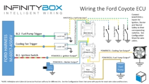
In the case of our customer’s 1967 Mustang, they are using the Ford Coyote crate engine.  That has a positive fuel pump trigger.  They chose to use an inVERT Mini to flip the positive signal from the ECU to a ground trigger to the MASTERCELL.  This picture shows the wiring diagram for the Coyote ECU and how the inVERT Mini is wired into the harness.

Image of wiring diagram showing how to wire the Ford Coyote ECU with the Infinitybox 20-Circuit Kit

Image of wiring diagram showing how to wire the Ford Coyote ECU with the Infinitybox 20-Circuit Kit

You can download a PDF of this Coyote wiring diagram by clicking this link.

Click on this link to contact our team with any questions about wiring your car with our Infinitybox system.  

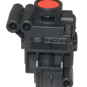
Picture of a fuel pump inertia switch

Inertia Switch

We just posted details on how to wire the fuel pump to our Infinitybox POWERCELL.  That was a very simple part of the wiring process in this 1967 Mustang.  We received a follow up question to this post about wiring a fuel inertia switch.  We’ll give details in this post.

A lot of manufacturers, Ford especially, use an inertia switch to interrupt the power going to the electric fuel pump in case of an accident.  These switches use an internal magnet and a ball bearing to close the circuit providing power to the fuel pump.  If there is a large impact to the car from a collision, the force of the impact knocks the ball out of its location.  This opens a set of contacts in the switch, which interrupts power going to the fuel pump.  These switches can be sensitive.  They may shut down the fuel pump if you get a flat tire or if you hit a large pot hole.  A lot of us here remember the prank of pounding on the driver’s rear fender in a mid-1990’s Thunderbird or Mustang to kill the fuel pump and leave a guy stranded.

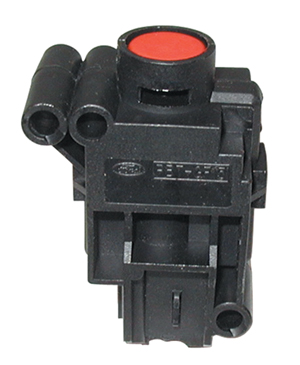
Picture of a fuel pump inertia switch

Picture of a fuel pump inertia switch

If there was an accident, this switch opens and cuts off power to the fuel pump.  There is a reset button on the top of the switch.  If the red plunger is up, that means that the switch tripped.  If you press down on the plunger, it will reset the switch, letting the electric fuel pump operate again.

In some cars, these switches are in the rear near the fuel pump.  In other cars, they are up front behind the dash.  Wiring an inertia switch to your fuel pump powered by our 20-Circuit Kit is really easy.

You can purchase these switches from any on-line source.  This link will take to you the popular Ford switch sold on Amazon.  You can find the switches but you can’t always find any data or specifications on them.

Switches are only designed to carry a maximum amount of current.  You always have to consider that when you choose a switch.  That is true when you pick your inertia switch.  These switches were designed to interrupt the feed going directly to the fuel pump.  This means that the switch was designed to carry the current for that pump.  In the case of this 1967 Mustang, we are installing a higher-performance pump that draws much more current that the original OEM pump.

To be safe, use the inertia switch to interrupt the MASTERCELL input wire for the fuel pump.  Each of our inputs only require a very small amount of current to operate.  The contacts in the inertia switch can easily handle the small amount of current from the MASTERCELL.

Under normal operation, the MASTERCELL input will be connected to a switch that turns on the input for the fuel pump.  This could be a signal coming from an ECU, it can be from a separate fuel pump switch or it can be tied to the ignition switch.  The inertia switch would be wired in series.  If there were to be an accident, the input from the MASTERCELL would be interrupted by the open contacts in the inertia switch.  This would cause the MASTERCELL to send the command to the POWERCELL to turn off the fuel pump output.  Wiring the switch in with the MASTERCELL input ensures that you will never overload the contacts on the inertia switch.

Click this link to contact our team with questions or comments on this post.


Wiring the FAST EZ-EFI

Our Infinitybox wiring harness can be used to provide switch electrical power to just about anything in your car.  This post shows you what you need for wiring the FAST EZ-EFI system.

First, installing any fuel injection system is a process.  Familiarize yourself with the instructions for the EZ-EFI system.  You can download them at this link.

Wiring the EZ-EFI is pretty straight forward.  You are going to use the ignition output on your POWERCELL to supply the switched 12-volts for the EFI system.  The MASTERCELL and POWERCELL in your 20-circuit harness replace the need for the relays to control the fuel pump and the cooling fan.  Connect the wires in their harness per this diagram.

Picture of wiring diagram showing how to wire the FAST EZ-EFI fuel injection system with the Infinitybox system.

Picture of wiring diagram showing how to wire the FAST EZ-EFI fuel injection system with the Infinitybox system.

It is important that you install the diodes that are shown in the diagram.  Our recommendation is to use a 1N4001 diode.  You can purchase these easily on-line.  Please note that the orientation of the diode is important.

You can download a PDF of this wiring diagram by clicking this link.

Give our technical support team a call at (847) 232-1991 if you have questions about wiring the FAST EZ-EFI system.