 Copyright Infinitybox, LLC 2021. All Rights Reserved.
 Headlights
In our last post, we hit the high-points of wiring the outputs on our Infinitybox POWERCELLs. Over the next few posts, we are going to go into detail on wiring some of the specific loads in your car. This post is going to talk about headlights.
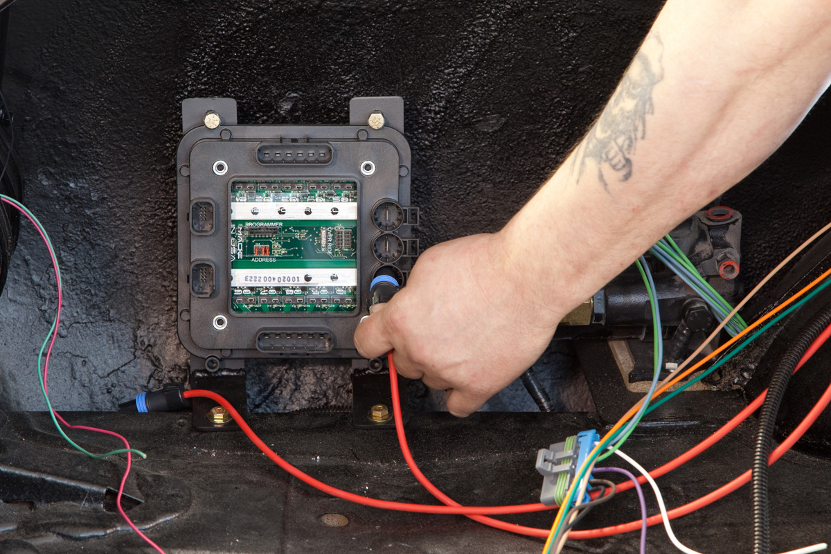
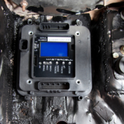
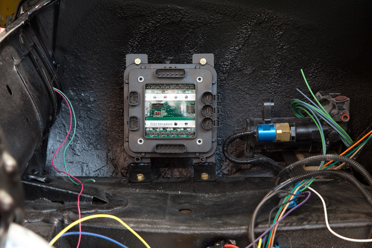
Headlights are usually the easiest output to wire and we use them as an example when we’re helping guys wire their cars over the phone. On the front POWERCELL, there is a dedicated output for the headlights. Check your configuration sheet for the exact wire color. This blog post will show you how to do this. In the case of our 1967 Mustang project, the POWERCELL output wire for the headlights is the white wire. This is output 5 on the B connector.
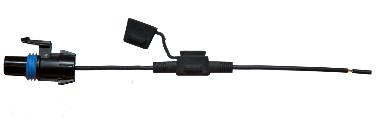
From the front POWERCELL, you are going to run the white output wire to your headlights. It is usually easiest to run the wire to the closest headlight, then splice from there to go to the second headlight. Essentially, you are wiring the two headlights in parallel. You can use our Splice Saver Kit to make this connection easy and reliable.
In the previous post about wiring POWERCELL outputs, we talked about ways to connect wires together. These options include butt-splicing, soldering and connectors. You can built the splice between the two headlight bulbs in this splice. This picture shows a simple schematic for wiring the two headlights off of a single POWERCELL output.
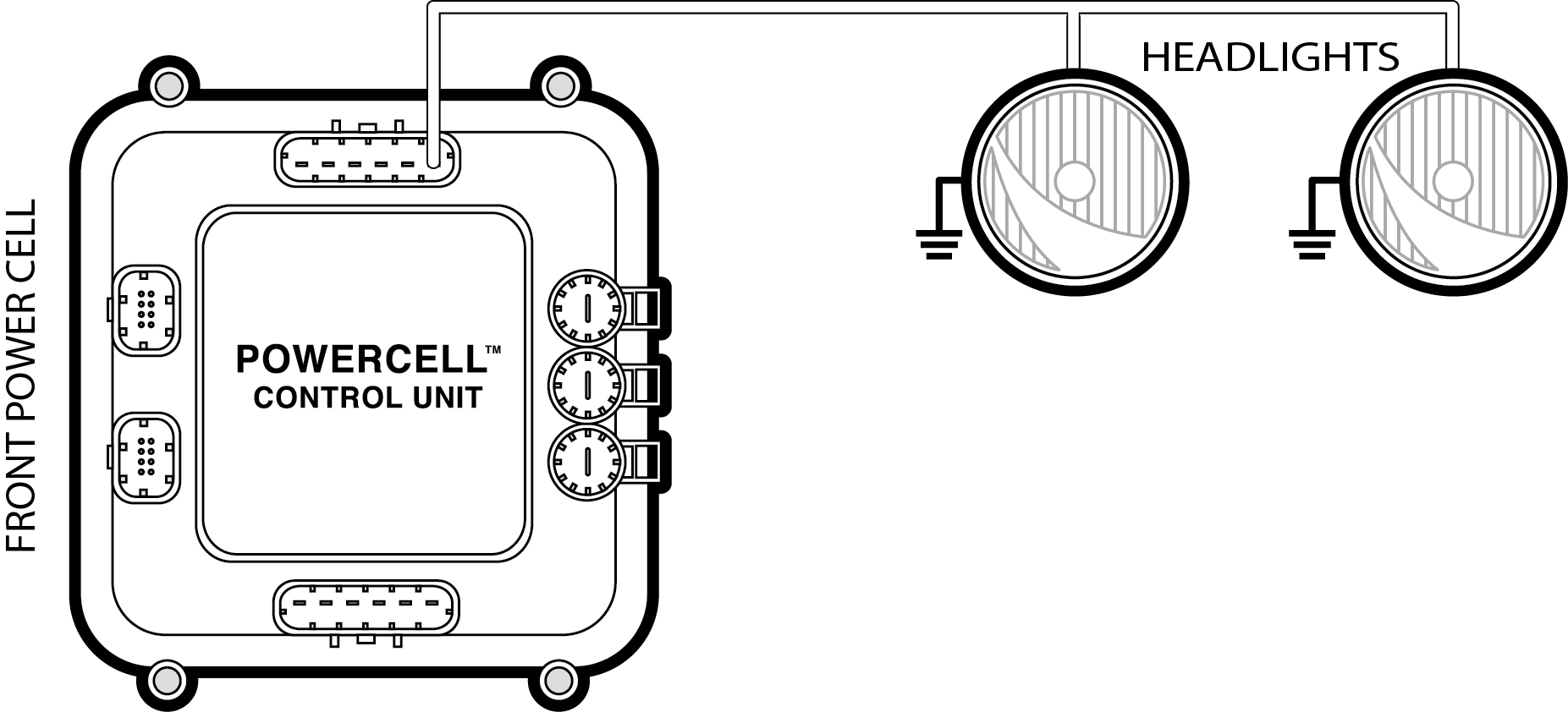
Picture of a simple schematic showing how to wire your headlights to the Infinitybox POWERCELL
There are going to be two wires on each of your headlights. One is the 12-volt power coming from the POWERCELL output. The other is ground, which needs to be connected to the chassis. If your high-beams are integrated into the same headlight housing, there may be multiple connections. You need to consult the paperwork or instructions that came with your headlights.
If your headlights are incandescent bulbs, the orientation of the power input and ground wires do not matter. The current will flow through the filament in the bulb in either direction. If you headlights are HID or LED, the polarity will matter. You need to consult the manual for the HID or LED headlight kit.
The standard headlight output on the front POWERCELL is designed for an incandescent bulb. We can do things with a POWERCELL output that you can’t do with a relay. Because we are using solid-state relays, we can do something called Pulse-Width Modulation. That means that we can gradually ramp up the power to an output.
Incandescent bulbs have a high in-rush current. When the bulbs are cool, the resistance of the filament is relatively low. When you first turn on the bulb, it will draw a lot of current. As the bulb and filament heat up, the resistance of the filament increases significantly, which limits the current to its steady-state draw. This inrush current can be 4 to 10 times the steady state current. You need to size you wire and the fuse to work with this inrush current. We have done that for you in our choice of output harness wire.
We soft-start the standard headlight and high-beam outputs on the front POWERCELL. This essentially smooths out the inrush, which causes less stress on the fuse, the wiring and the light bulb. You get this feature automatically if you use the standard MASTERCELL input.
You can use this same soft-starting output for LED (Light Emitting Diode) headlight kits. If you are using HID (High Intensity Discharge) headlights, you need to use a different input to the MASTERCELL. There is a dedicated input to the MASTERCELL for HID headlights. If you use this input, the headlight input turns on instantaneously without the soft starting. We’ll talk more about MASTERCELL inputs in later posts.
While we’re at it, you are going to wire your high-beams exactly the same way as the headlights. In the case of the configuration that we are using for this 1967 Mustang, the dark-blue wire from the front POWERCELL is for the high-beams. This is output 7 on the A connector. You are going to run the high-beam output from the POWERCELL to the first high-beam bulb then splice over to the second high-beam bulb. Check the documentation that came with your bulbs for proper wiring. The ground wire on the bulb should connect to the chassis of the car.
Keep watching our blog for more posts on wiring the different outputs on your Infinitybox wiring system. Click this link to contact our team with questions.
 Copyright Infinitybox, LLC 2021. All Rights Reserved.
 Copyright Infinitybox, LLC 2021. All Rights Reserved.
 Copyright Infinitybox, LLC 2021. All Rights Reserved.
 Copyright Infinitybox, LLC 2021. All Rights Reserved.