Posts

Back-Up Lights

The back-up lights are the next thing to wire in our customer’s 1967 Mustang project.  We’re getting to the end of the switches that we need to wire to the MASTERCELL.

If you look at your configuration sheet, you will not see a dedicated output for back-up lights.  Depending on the vintage of the car and the manufacturer, there may or may not be back-up lights on the car.  We don’t dedicate an output to this but you can use any of the OPEN outputs on your rear POWERCELL.

This link will take you to the configuration sheet for the system that we are installing in this 1967 Mustang.  This link will take you to our previous post in this series going through the details of the configuration sheet.  You will see that there are several outputs that are labeled as OPEN on the configuration sheet.  Depending on the version, you may have 4 to 6 OPEN outputs.  OPEN means that there is no specific function assigned to the output.  These can be used as generic outputs.  You will note that the personality for these outputs is TRACK.  That means that the output will track the switch.  When the switch is on, the output is on.  When the switch is off, the output is off.  You can use OPEN outputs for things like amp triggers, extra lights, transmission cooler fans, secondary fuel pumps and back-up lights.

Output 5 on the rear POWERCELL is OPEN.  This is the white wire coming from the B harness.  The MASTERCELL input is the white wire with the red wire.  This is input 2 on the MASTERCELL A input harness.

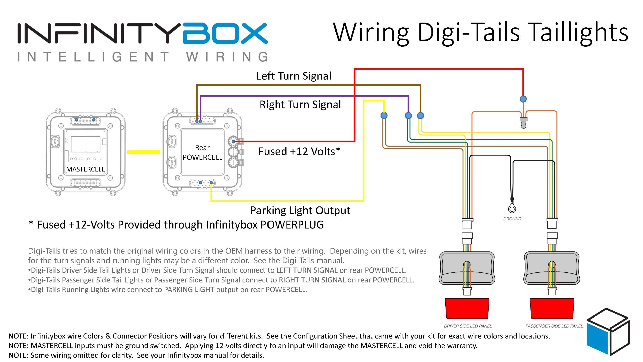
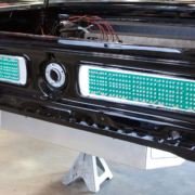
We previously connected the white wire from the rear POWERCELL to the back-up lights in the rear of the car.  The customer is using the tail light assembly from Mustang Projects.  You can read about that in this blog post.  The white wire connects to the tail light assembly.  Then the assembly needs to get connected to ground.  Follow the instructions that came with your back-up lights for the exact wire colors.

Next, the MASTERCELL input wire needs to connect to a switch that closes when the transmission is in the reverse position.  Our customer is using a Ford AOD transmission in this car.  There is a dedicated connector on the driver’s side of the transmission.  We connected to this connector in a previous post for the neutral-safety signal.  We are going to connect to the same connector for the reverse signal.

Sketch of the Reverse/Neutral Safety Switch Connector on a Ford AOD Transmission

Sketch of the Reverse/Neutral Safety Switch Connector on a Ford AOD Transmission

This diagram will show you which terminals on the Ford AOD transmission you need to connect to ground and to the MASTERCELL input harness.

Wiring diagram for Reverse/Neutral Safety switch on Ford AOD transmission

Wiring diagram for Reverse/Neutral Safety switch on Ford AOD transmission

Terminal 1 on the transmission connector needs to get connected to ground.  Terminal 2 needs to connect to the MASTERCELL input for the back-up lights.  In our case, this is the white wire with the red tracer on the MASTERCELL A input harness.  This link will take you to a PDF of this document.

When the transmission is in the reverse position, the switch makes a connection between terminals 1 and 2.  This connects the MASTERCELL input to ground.  When the MASTERCELL sees the input connect to ground, it sends a signal to the POWERCELL in the rear of the car to turn on the output that we have chosen for the back-up lights.  When the transmission is taken out of reverse, the switch opens which disconnects the MASTERCELL input from ground.  The MASTERCELL sees this change and sends a command to the POWERCELL to turn off the output that we have chosen for the back-up lights.

Most transmissions will have a set of contacts for a reverse switch.  In other cases, there will be a switch in the shifter that will be made when the transmission is in the reverse position.  Check the literature that came with your transmission or your shifter.

That’s it.  Having a POWERCELL in the rear of the car makes wiring the back-up lights very easy.  There is no extra wire to run to the back of the car.  You are already using the existing POWERCELL to manage this.

Please contact our team with any questions about wiring with our Infinitybox system.  You can contact a member of our technical support team by clicking this link.

Turn Signals with a Trailer Converter

A common question that we get relates to wiring turn signals with our 10-Circuit Kit.  A lot of guys want to know if they can wire their cars or trucks with a 10-Circuit Kit instead of a 20-Circuit Kit.  We put up a post on our blog a while ago talking about the benefits of one kit over the other.  You can read that at this link.

For guys wiring with the 10-Circuit Kit, a lot ask about how to get our 1-filament turn signal feature when there is only one POWERCELL in the system.

Our standard 20-Circuit Kit gives you several different options for your turn signals in the rear of the car or truck.  This link will get you more detail.  The option that raises the most questions is what we call 1-filament turn signals.  This version uses one filament from a bulb on both sides of the rear of the car to be both the turn signal and the brake light.  The easiest way to check for this is by the color of the lenses on your rear turn signals.  If they are red, you probably have a one filament configuration.  If they are amber, you’d use what we call multi-filament.

To manage what we call 1-filament turn signals, the POWERCELL turns on both the left and right turn signal outputs at the same time when you step on the brake light.  We also have special software in the system that will let one turn signal override the brake light if you have a turn signal on while stopped.  With our 20-Circuit Kit, you have two POWERCELLs in the system.  The turn signals coming off of the rear POWERCELL act differently than the turn signals on the front POWERCELL.

When you wire your car with our 10-Circuit Kit, you only have one POWERCELL in the system.  This means that you have only one pair of outputs controlling your turn signals.  You cannot control 1-filament turn signals directly from a single POWERCELL.  If you did, your front turn signals would both turn on when you stepped on the brake pedal.

To wire 1-filament turn signals with our 10-Circuit Kit, you need to add a Trailer Light Converter to your wiring harness.  These are simple controllers that replicate what we are doing in software for the 1-filament turn signals.  This schematic shows you how to wire in a trailer light converter to a 10-Circuit Kit.

Picture of wiring diagram showing how to use a trailer converter with the Infinitybox 10-Circuit Kit.

Picture of wiring diagram showing how to use a trailer converter with the Infinitybox 10-Circuit Kit.

There are lots of different companies that make trailer converters.  Our customers have recommended these two options.

Tow Ready 119130

Hopkins 48895

Contact us if you have any questions about wiring your turn signals.  You can download the application note in PDF format by clicking this link.

Picture of Digi-Tails Sequential Tail Lights

Digi-Tails

Our Infinitybox system is designed to control about anything electrical in your car, truck or custom vehicle.  Here’s an example of wiring tail lights manufactured by Digi-Tails.

Digi-Tails makes a very broad range of LED tail light assemblies for a full range of vehicles.  If you’re building it, they probably have a kit for your car.  This includes Mustangs, Camaros, Tri-Fives, MOPAR and most anything else.  They make traditional and sequential kits.  You can check out their full product line here.

Wiring their kits with your 10-Circuit or 20-Harness from Infinitybox couldn’t be simpler.  The bottom line is you wire their assemblies just like you would wire the traditional tail lights that came with your car.  They have a wire for the parking lights, the left turn signal and the right turn signal.  You connect those wires to the same outputs on the rear POWERCELL.  Connect your MASTERCELL input wires to the turn signal stalk and the brake pedal and you’re ready to go.

Digi-Tails tries to match the original wiring colors in the OEM harness to their wiring.  Depending on the kit you have from them, the wires for the turn signals and running lights may be a different color.  Here’s how you want to match your POWERCELL output wires to their wires.

  • Their Driver Side Tail Lights or Driver Side Turn Signal should connect to the LEFT TURN SIGNAL from your rear POWERCELL.  In most Infinitybox kits, this is the brown wire but always check your configuration sheet.
  • Their Passenger Side Tail Lights or Passenger Side Turn Signal should connect to the RIGHT TURN SIGNAL from your rear POWERCELL.  In most Infinitybox kits, this is the violet wire but always check your configuration sheet.
  • Their Running Lights wire should connect to the PARKING LIGHT output from your rear POWERCELL.  In most Infinitybox kits, this is the yellow wire but always check your configuration sheet.

The only real difference when wiring a Digi-Tails tail light panel is that they need a constant 12-volt power feed to power the electronics on their LED board.  In most of their kits this is the orange wire going to each tail light assembly.  Check their manual for the specifics of your kit.  You can easily do this with one of our POWERPLUG 12-volt accessories.  This simply plugs into one of the unused power ports on your rear POWERCELL.  It has an integrated fuse holder to properly protect the wire against getting shorted to ground.  In this case, we’d recommend fusing that wire with a 5-amp fuse.  You can learn more about the POWERPLUG at this link.

When using the Digi-Tails tail lights, you want to use the MASTERCELL inputs for 1-filament.  By doing this, you are setting the system to manage the turn-signals and the brake lights together on the same outputs.  This link will take you to an older blog post that talks about our different turn signal options.

Here is a simple diagram that shows you how to connect the outputs from your rear POWERCELL to any of the Digi-Tails tail light kits.

Picture of a wiring diagram showing how to wire Digi-Tails Sequential Lights with Infinitybox

Picture of a wiring diagram showing how to wire Digi-Tails Sequential Lights with Infinitybox

You can download a copy of this diagram by clicking this link.

Contact our technical support group if you have questions about wiring your Digi-Tails with our Infinitybox system.