Wiring turn signals, 4-ways and the horn to the MASTERCELL in your Infinitybox system is very easy. Our inputs can connect to the connectors of any steering column. This blog post is going to cover the IDIDIT Mustang Steering Column wiring. Specifically, this is for their 1965 & 1966 columns.
Before you go too far, be sure to read and understand the instructions for installing your column. You can download the IDIDIT instructions for this Mustang column by clicking here. IDIDIT gives you the connector components to plug directly into the original harness in your Mustang. The difference with our Infinitybox system is that your MASTERCELL inputs are going to wire to the switches on the column. The switches on the column become triggers to the MASTERCELL. Our Infinitybox system takes care of the rest.
This diagram will show you which MASTERCELL input wires need to connect to the terminals on the IDIDIT column.
Picture of a wiring diagram showing how to wire the IDIDIT Mustang steering column to the Infinitybox MASTERCELL
Please note that this diagram does not give you the MASTERCELL input wire colors. You need to line up the function on the column to the wire color on your configuration sheet. Depending on your system and your accessories, you may have different wire colors for your inputs. Click on this link to learn more about your configuration sheet.
The connections between the Infinitybox MASTERCELL and the connector on the column are easy. Essentially, you only need to connect the inputs for your left turn signal, right turn signal and the horn. Then you need to ground two of the column wires to the chassis. That’s it.
We spend a lot of time educating customers on what a MOSFET is and why it is better than a mechanical relay. All of the outputs on our POWERCELLs are controlled by MOSFETs. They are more efficient than relays, they generate less heat, the have no moving parts, they never wear, we can PWM outputs, etc. The lists of benefits can go on for hours. One of the biggest advantages of a MOSFET can also be a disadvantage. Since it has no moving parts, it makes no noise when it turns on and off. In the case of turn signals, that can be a disadvantage.
In a traditional wiring system, electro-mechanical flasher modules are used to flash the turn signals. These are typically bi-metal devices that have been around since the dawn of the automotive industry. When you turn on your flashers, current flows through a element in the flasher module. This heats up a special combination of metals laminated together. After a short period of time, this element flexes and separates a contact. When it separates, the current stops flowing and the element cools down. This lets the element snap back to its starting position which makes the connection again. The element heats up and the cycle repeats over and over until your turn your signals off. The mechanical movement of this element in the flasher module is what makes the clicking sound.
This video shows how it works. Thanks to Chris at Mustang Restorations in Dundee, Illinois for creating this.
You may have noticed in most new cars that the turn signals sound different from most classic cars. All new cars are using multiplexing technology similar to our Infinitybox system. This means that they are replacing the traditional flasher module with MOSFET control. They have tone generators behind the dash that create a synthetic turn signal sound.
Just a quick note about the video above. If you carefully watch the contacts in the flasher module after Chris removes the cover, you will can see arcing (little sparks) between the contacts as the flasher cycles on and off. This arcing gradually erodes the contacts in the flasher and causes them to fail over time. Since our POWERCELL outputs use solid-state MOSFETs, there are no moving contacts to arc and erode over time. You can flash your turn signals billions of times with no change in their performance.
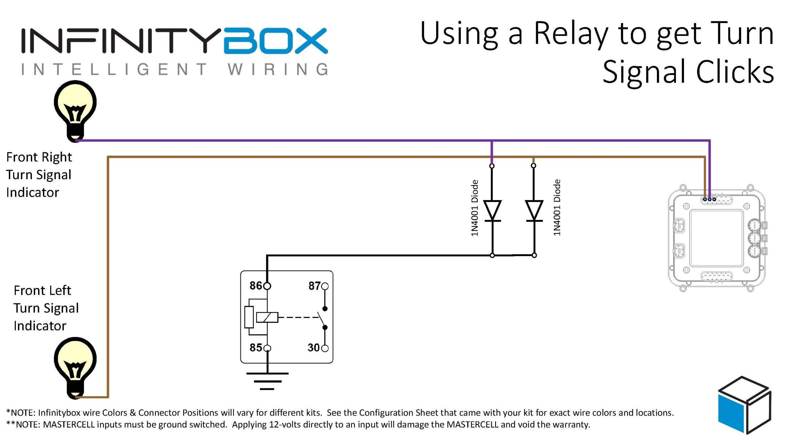
Image of wiring diagram showing how to wire the Infinitybox system to get sounds with your turn signals
You are going to add a relay behind your dash. This isn’t going to carry any current, you’re just going to use the mechanical action of the relay to make a clicking sound. You simply tap off of your POWERCELL outputs for your left and right turn signals. These get wired to the coil of a relay through two diodes. These diodes are very important because they isolate the two turn signal outputs from each other. Without these diodes, both of your turn signals would be connected electrically and would turn on together. These diodes should be 1N4001. You can easily get them from Amazon. The orientation of these diodes is critical. Please note the position of the cathode in the wiring diagram. This will not work if they are not oriented correctly.
For all standard relays, the coil terminals are 85 and 86. Connect your turn signal outputs through the diodes to terminal 86, then ground terminal 85 to the chassis.
We recommend a relay like this one.
Example of an automotive 12-volt SPDT Relay
You can purchase this relay and its terminals at Waytek Wire. This is a good relay to use because it has an integrated mounting tab. That makes it easy to mount behind your dash. It also will help sounds to travel from the relay contacts to resonate your dash. You want to mount this in a place behind your dash to get good sound transfer. You may have to experiment with different locations to get the loudest results.
Here’s how this works. When you flip on your turn signal, the POWERCELL flashes the turn signal outputs. Power from the outputs flows into the coil of this relay. This pulls in the relay contact and makes a click. When the POWERCELL flashes the turn signal off, power is taken away from the relay coil. The contacts snap back to their rest position and make another click. This relay isn’t carrying any power, it is just making noise.
A common question that we get relates to wiring turn signals with our 10-Circuit Kit. A lot of guys want to know if they can wire their cars or trucks with a 10-Circuit Kit instead of a 20-Circuit Kit. We put up a post on our blog a while ago talking about the benefits of one kit over the other. You can read that at this link.
For guys wiring with the 10-Circuit Kit, a lot ask about how to get our 1-filament turn signal feature when there is only one POWERCELL in the system.
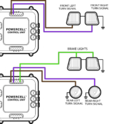
Our standard 20-Circuit Kit gives you several different options for your turn signals in the rear of the car or truck. This link will get you more detail. The option that raises the most questions is what we call 1-filament turn signals. This version uses one filament from a bulb on both sides of the rear of the car to be both the turn signal and the brake light. The easiest way to check for this is by the color of the lenses on your rear turn signals. If they are red, you probably have a one filament configuration. If they are amber, you’d use what we call multi-filament.
To manage what we call 1-filament turn signals, the POWERCELL turns on both the left and right turn signal outputs at the same time when you step on the brake light. We also have special software in the system that will let one turn signal override the brake light if you have a turn signal on while stopped. With our 20-Circuit Kit, you have two POWERCELLs in the system. The turn signals coming off of the rear POWERCELL act differently than the turn signals on the front POWERCELL.
When you wire your car with our 10-Circuit Kit, you only have one POWERCELL in the system. This means that you have only one pair of outputs controlling your turn signals. You cannot control 1-filament turn signals directly from a single POWERCELL. If you did, your front turn signals would both turn on when you stepped on the brake pedal.
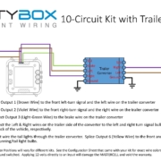
To wire 1-filament turn signals with our 10-Circuit Kit, you need to add a Trailer Light Converter to your wiring harness. These are simple controllers that replicate what we are doing in software for the 1-filament turn signals. This schematic shows you how to wire in a trailer light converter to a 10-Circuit Kit.
Picture of wiring diagram showing how to use a trailer converter with the Infinitybox 10-Circuit Kit.
There are lots of different companies that make trailer converters. Our customers have recommended these two options.
https://www.infinitybox.com/wp-content/uploads/2021/02/Trailer-Converter-Image-scaled.jpg14402560adminhttps://www.infinitybox.com/wp-content/uploads/2021/02/infinitybox-logo-https-1-1.pngadmin2016-04-01 07:47:532021-02-23 07:55:32Turn Signals with a Trailer Converter
We get a lot of questions about wiring turn signals. Our MASTERCELL inputs are very flexible. These let you connect practically any switch to the Infinitybox system. We have other blog posts that show you how to wire GM-style steering columns to the Infinitybox MASTERCELL. You can check that out here. Flaming River columns and IDIDIT columns use the exact same connector so you can use the same instructions.
We got a call from a customer installing a TS1342 turn signal switch sold by Limeworks. This is a very classy turn signal switch with a very retro look. There are two versions: one for a 1 1/2″ column and one for a 1 3/4″ column. It also has a lit end that can be used as a turn signal indicator if you don’t have one on your dash.
The customer asked about how to wire the turn signal switch into his Infinitybox MASTERCELL. It’s is such a good question, we created a new application note for it and posted it.
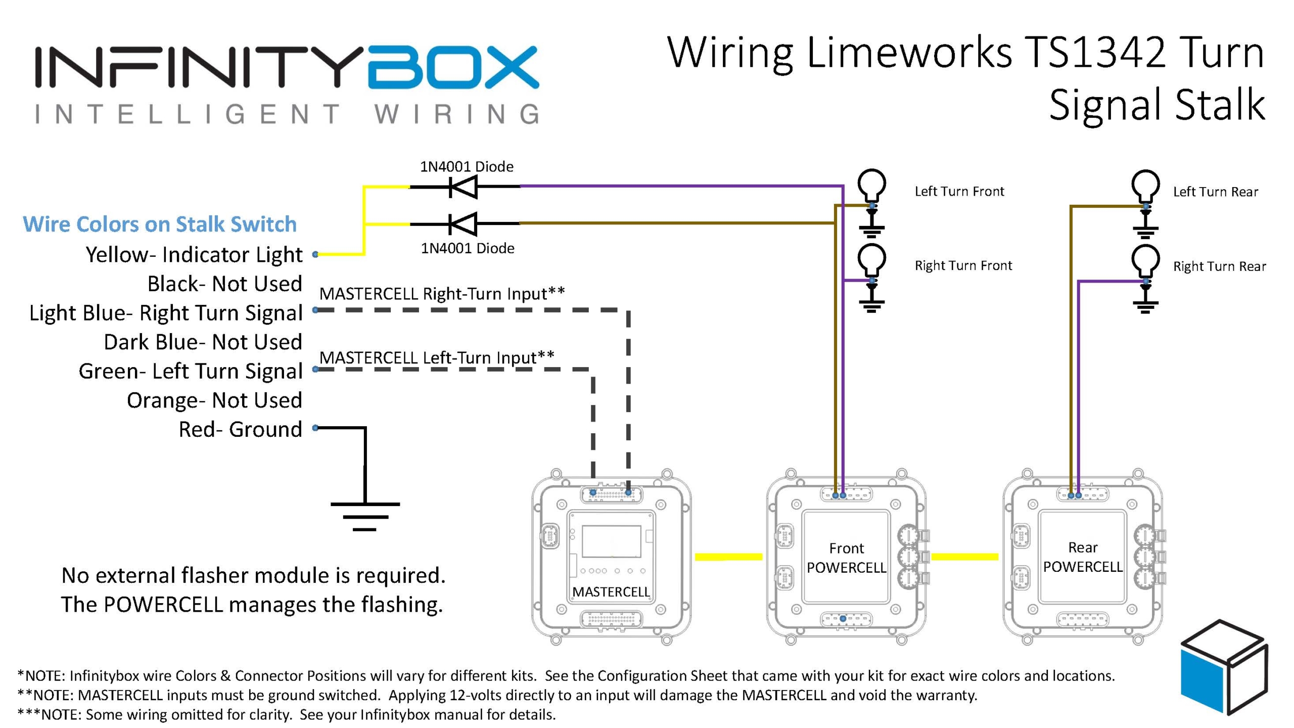
The wiring diagram that comes with the switch shows the need to use a 3-prong flasher module. You need this if you’re connecting it to a traditional wiring harness. If you’re connecting it to our Infinitybox system, you don’t need the flasher. We build that into the system so no external flashers are required. This diagram shows you how to connect the Limeworks TS1342 turn signal switch into the Infinitybox system.
Picture of wiring diagram showing how to wire the Limeworks TS1342 turn signal switch with the Infinitybox system.
The MASTERCELL inputs work by getting connected to ground. This column switch was designed to supply battery voltage to a flasher, which fed the turn signal bulbs. As we said above, we can eliminate the flasher. To make it work with the MASTERCELL inputs, you simply ground the wire on the switch that was connected to the battery. The two wires that connected to the left and right turn signals will connect to their respective inputs on the MASTERCELL. That’s it. When you push the switch to the left, you’re electrically connecting the former power wire to the left turn signal input. Since the former power wire is grounded, the left turn signal input wire gets connected to ground. The MASTERCELL sees this and tells the POWERCELLs to flash the left turn signal. The same thing happens for the right turn signal. The diagram shows you which wires on the switch need to connect to the MASTERCELL inputs. Use the configuration sheet that came with your kit as a guide to identify the MASTERCELL wire colors.
The other thing that you’ll notice in our wiring diagram is that the brake pedal switch doesn’t get connected to the turn signal switch. The original wiring diagram had that because the brake pedal jumpered the left and right turn signals together for the brake lights. This is something that we manage within the MASTERCELL. If your rear turn signals are also your brake lights, you simply use the MASTERCELL input that is assigned to the 1-filament brake lights and connect that to your brake pedal switch.
The last thing to talk about in this post is turn signal indicators. Depending on your gauges, you can handle this a few different ways. If you have turn signal indicators on your dash, we recommend splicing off the left and right turn signal outputs on the front POWERCELL and connect them to the indicators. Most turn signal indicators draw very little current so you can run a light gauge wire, like 22-AWG from the POWERCELL outputs to the indicators. If you’re using LED’s make sure that you’re paying attention to their polarity. Also, check the voltage rating of your LED’s. Most are rated to 5 volts or less. You may have to add a resistor in series to limit the current flowing through the LED. Give our tech guys a call if you have question here.
One of the cool things about the TS1342 is that it has an indicator light on the tip of the stalk. It can flash when the turn signals are flashing. To do this, you need to splice off the POWERCELL outputs for the left & right turn signals like I mentioned above. Since there is only one light, you need to connect the outputs together. However, you need to put diodes in the circuit to isolate the left turn signal from the right. Without these diodes, the left turn signal would flash when the right was flashing and vice veat companies like www.digikey.com or www.mouser.com. Or you can pick these up at a Radio Shack if they are still open where you are. See the diagram for details on how to install these diodes. Remember, the orientation of the diodes is critical.
We get a lot of questions about turn signals and brake lights. There are two options in our standard front-engine configuration: Mechanical Multi-Filament and Mechanical Single-Filament. This is where there is sometimes some confusion. In both cases, this is where you use a traditional steering column with the canceling mechanism built in. This can be an OEM column or one from an aftermarket company like IDIDIT or Flaming River. In both cases, the mechanism in the column turns off the turn-signal action when the steering wheel returns to the center position.
The mechanical column, multi-filament configuration should be used when you have separate filaments in the rear of the car for the turn-signals and the brake lights. These could be completely separate bulbs or different filaments in a multi-filament bulb. The inputs to the MASTERCELL control separate outputs for left & right turn-signals plus the brake light. There is a good rule of thumb for multi-filament turn-signals: if your turn-signals are amber, you should probably be using the multi-filament configuration.
The mechanical column, single-filament configuration should be used when the brake lights share a common filament with the turn-signals in the back of the car. Remember that you need to look at the filaments, not the bulbs. In this case, the MASTERCELL inputs will activate the left and right turn-signals as directionals. You only wire the left and right turn-signal wires to the bulbs. No brake light output is required. For the brake light, the left and right turn-signal filaments light together.
Once you figure out what you need in the car, you just pick the inputs that you need and wire them to the column. This schematic will show you how to wire the MASTERCELL inputs to the GM, IDIDIT and Flaming River columns.
For all of those guys building a Factory Five GTM with the C5 Corvette steering column, here is how you connect the Infinitybox MASTERCELL inputs to the column harness.
Connect these pins to the MASTERCELL inputs:
Pins D, Z, X & W – Connect to Ground
Pin V – Horn input to MC
Pin R – Park lights input to MC
Pin L – Low Beam input to MC
Pin K – High Beam Input to MC
Pin G – Left Turn Input to MC
Pin F – Right Turn Input to MC
Depending on which turn-signal style you want (1-filament vs. multi-filament), refer to your configuration sheet for the specific wire colors. You can download the Infinitybox GTM Configuration Sheet by clicking here.
https://www.infinitybox.com/wp-content/uploads/2021/02/MASTERCELL.jpg17601800adminhttps://www.infinitybox.com/wp-content/uploads/2021/02/infinitybox-logo-https-1-1.pngadmin2015-05-14 11:45:062021-08-23 13:46:28Wiring MASTERCELL Inputs to the GTM Column


 Copyright Infinitybox, LLC 2021. All Rights Reserved.
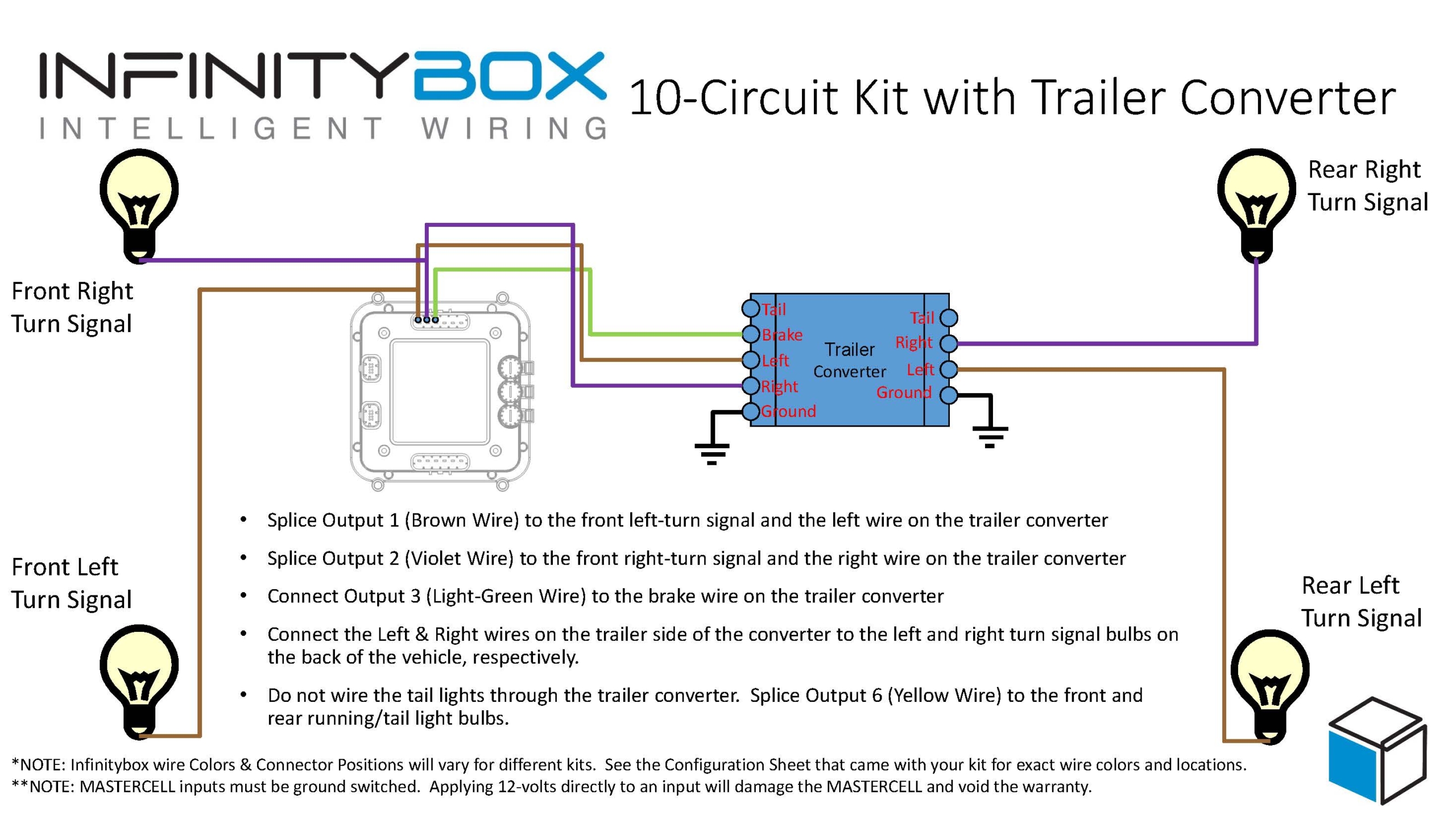
 Copyright Infinitybox, LLC 2021. All Rights Reserved.
 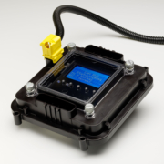 The Infinitybox MASTERCELL