
E-Stopp Emergency Brake System Wiring
Here is another installment in our series showing how the Infinitybox system plays nicely with other electronics systems. A lot of you have asked how to wire the E-Stopp Push-Button Emergency Brake System so here’s the answer. It is really easy. Learn how to do it in this blog post plus download a wiring diagram showing what connections that you need to make. The E-Stopp Push-Button Emergency Brake System gives you a slick way to control the emergency or parking brakes in your muscle car, restoration, street-rod, resto-mod or pro-touring build. From a single push button, you can engage and disengage your emergency brakes. Their kit gets you a linear actuator that tensions the brake cable and a control module that manages the push button and the linear actuator. You can learn more about their products at their website by clicking this link.
Just like any other project, you must carefully read and understand the instructions before you start to install it. Please review the manual that came with your E-Stopp System or download it from their website by clicking here.
This blog post is going to describe the wiring details between the E-Stopp controller and the Infinitybox system. Follow their instructions for details on how to connect the linear actuator to their controller. Also, follow their instructions for connecting battery power and ground to their controller.
The connections between your Infinitybox system and your E-Stopp controller are very simple. Their controller needs a signal that lets it know if the ignition is on. If the ignition is on, their controller will not let you engage or disengage the emergency brake. This is a very important safety feature. This picture shows the connection between the Infinitybox ignition output and the Blue “Safety to Ignition” wire going to the E-Stopp controller.
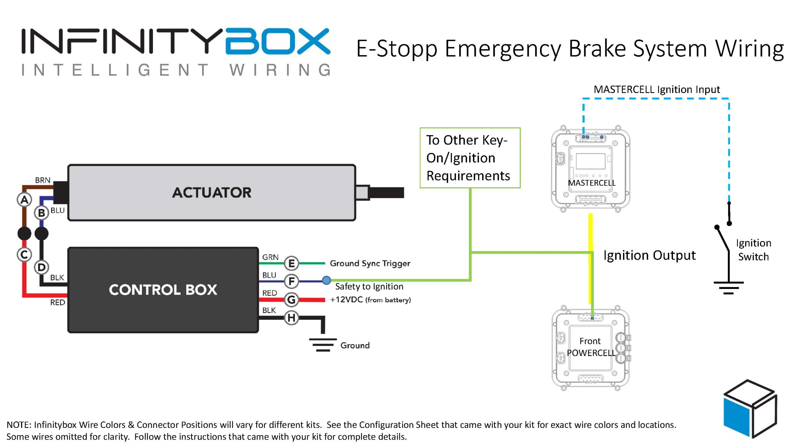
Picture of wiring diagram showing how to wire the E-Stopp Push-Button Emergency Brake System with the Infinitybox system.
You can get this ignition signal from the Ignition output on your Infinitybox system. In most systems, this output 3, which is the light green output on the front POWERCELL. Please check your specific configuration sheet that came with your Infinitybox kit. You are going tap off your ignition output to get this safety signal. Your ignition output is also powering you coil, ECU, EFI system, gauges and other key-on accessories. You can simply splice into this wire to connect it to the E-Stopp. You can also use our Splice Saver Kit to make this connection. This picture shows you how you’d make this connection with the Splice Saver.
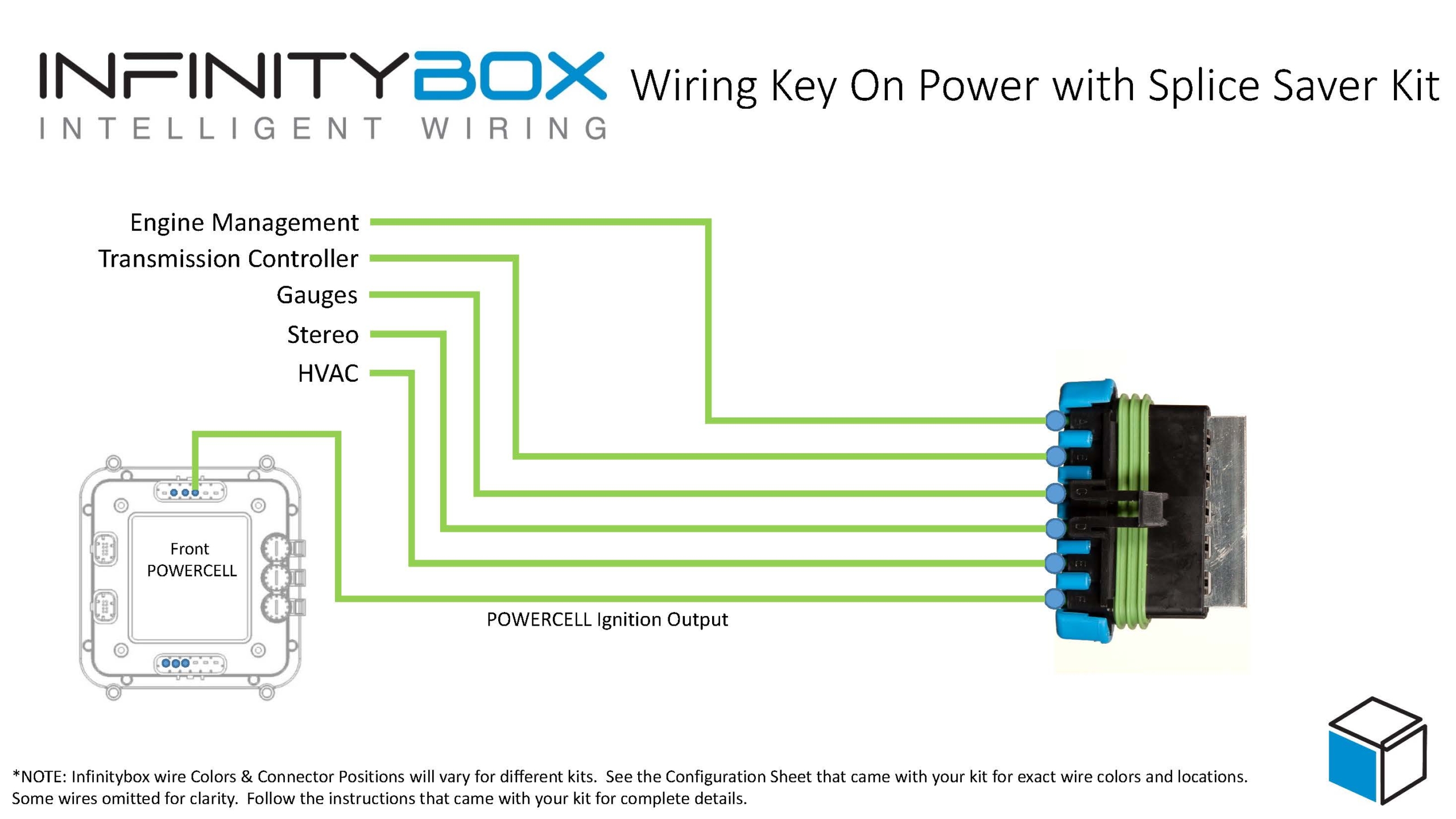
Wiring ignition key-on power with the Infinitybox Splice Saver Kit
Outside of that, wiring the E-Stopp Emergency Brake System with the Infinitybox system is easy. You can download a PDF version of the wiring diagram by clicking here.
Give our team a call at (847) 232-1991 with any questions about this wiring diagram. You can also contact us directly by clicking this link.