Now it is time to connect the POWERCELL outputs to your loads in the car. When we talk about loads, we refer to the things that you need to power to make the car work. These include your headlights, turn signals, ignition systems, starter solenoids, fuel pumps, cooling fans, horns, lights, etc. All of these loads are going to the connect to each POWERCELL output to get their switched battery power.
This post is going to cover the basics of wiring the POWERCELL outputs. We will publish several specific posts that will go through the details of how to wire your turn signal outputs, wiring your ignition and starter, wiring cooling fans and other loads.
The automotive electrical system uses a grounded chassis. This means that each load gets its switched power from some power distribution device. In your case, it is your POWERCELL. Current flows from the POWERCELL to the load. To complete the circuit, the load needs to get connected to ground, which is typically your chassis. The chassis is connected to the negative post of the battery. This is how the circuit is completed in your system.
Another thing to remember about your Infinitybox system is that the switches connect to the MASTERCELL. Your loads connect to the POWERCELLs. There is no connection between the switch and the load. That connection comes from a data command sent from the MASTERCELL to the POWERCELLs. When you turn on a switch, the MASTERCELL tells the POWERCELL to turn on an output.
Your kit includes an A & B output harness for each POWERCELL. If you have our 10-Circuit Kit with one POWERCELL, you have one each of the A & B harnesses. If you have our 20-Circuit Kit with two POWERCELLs, you will have two of each.
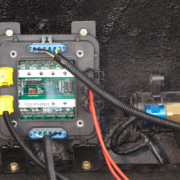
This picture shows you the POWERCELL A output harness. It has the wires for outputs 6 through 10.

POWERCELL A Output Harness
This picture shows you the POWERCELL B output harness. It has the wires for outputs 1 through 5.

POWERCELL B Output Harness
Yes, we get that it seems that the A & B designations are reversed for these harnesses. That designation came from the original layout of the POWERCELLs from our early beginnings. These designations have stuck and changing over a decade of documentation would be tough.
Please note that the A & B connectors are interchangeable in the POWERCELL output sockets. A lot of initial problem calls that we get from customers come from the fact that they have these harnesses reversed. Make sure that you are plugging the correct harness into the correct socket. The manual that came with your kit shows you the correct orientation. This picture also shows which connector socket is A & B.

Illustration of Infinitybox POWERCELL labeling output connectors
Once you get the connectors plugged into the correct sockets, you need to properly ground the POWERCELLs. Each of of the output harnesses have a black wire. Both of these black wires need to get grounded to the chassis. This is to properly ground the electronics in the POWERCELL. Make sure that you have a good metal-to-metal connection between these ground wires and the chassis. You must make sure that you remove all dirt, rust, oil, grease, paint and powder coating from this connection.
Next, it is time to start connecting the POWERCELL output wires to the loads in the car. Remember that your configuration sheet is your road map to do this. You can review our previous blog post about the configuration sheet as a refresher by clicking this link. The configuration sheet is going to identify the specific POWERCELL output wire by color for each load in the car.
You are going to run the POWERCELL output to the load. From there you must connect the POWERCELL output wire to the wiring on your light, fan, horn, fuel pump, etc. There are many different ways to do this. People will argue advantages of one method over another. If done correctly with the right tools, they are all good methods.
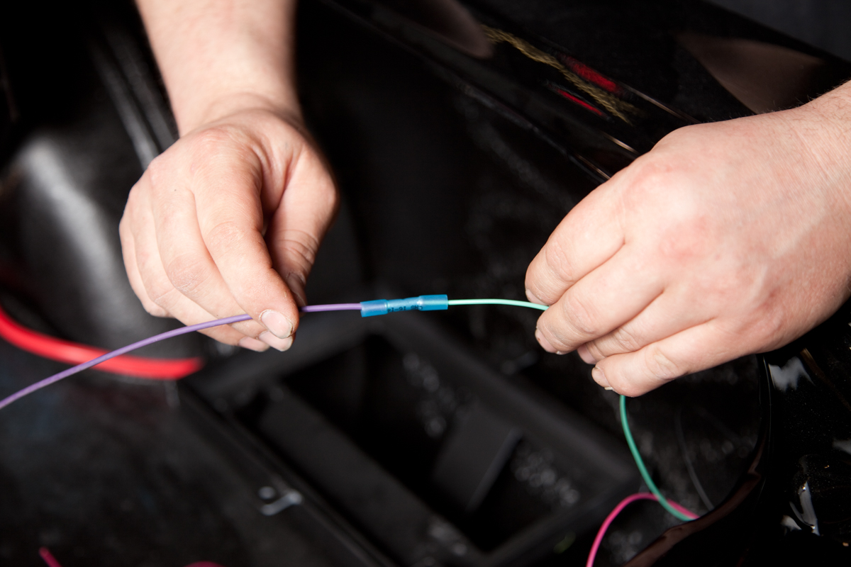
One of the easiest ways is to butt splice the POWERCELL output wire to the wire on your load. For example, you cooling fan will probably have two wires coming from the motor housing. You can use a butt splice connector to connect the POWERCELL output wire to the wire on the fan motor. This picture shows an example of a butt-splice.

Picture showing example of splicing wires in our 1967 Mustang Install of the Infinitybox wiring system.
The team at Waytek Wire have a great post on their blog called “Splice Connectors 101”. In this article, they walk you through the basics of splicing wires together. Click here to read this article.
What is important is that you use the correct crimp tool and you properly seal the joint. This seal can be done with heat shrink tubing or you can use butt crimp connectors that already have a heat-shrink jacket over them. Companies like Waytek and Del City are great sources for the right tools and materials.
Another option is to solder the wires together. A lot of customers swear by this method or a combination of butt-splicing and soldering. The advantage is that you get a metallurgical connection between the copper strands of both wires. Some will argue that this is stronger and more reliable than a pure mechanical crimp of a butt-splice. Just like the butt-splice mentioned above, this joint must be sealed preferably with heat shrink. The only warning with soldering is that if too much solder is applied to the joint, it can wick up the strands of the wire flowing away from the joint. This wicking can make the wire more rigid and susceptible to fatiguing if the joint is stressed mechanically. Just watch the amount of solder that you are applying to the joint.
The last is to put connectors on both ends of the connection. This is the most time consuming and costly, but it has advantages down the road if you need to remove the load for maintenance. There are many different options for connection systems. Deutsch connectors are very popular in racing. They are rugged, durable and proven. Delphi Weatherpack connectors are another option. They have been proven in the field for decades and are a cost effective option. You can purchase Weatherpack kits from many different sources that include the proper tools to crimp the terminals. Here is an example of a Weatherpack kit that includes the tool.
If the POWERCELL output harnesses are not long enough, you can easily extend them using any of the connection methods mentioned above. You must make sure that you use the right size of wire and the right insulation type. We use 14-AWG wire for all of the POWERCELL outputs. This will carry 32-amps continuously, which is very conservative for most aftermarket and racing applications. We use wire with TXL insulation. This is a cross-linked wire designed for the automotive environment. It is oil, dirt, chemical and abrasion resistant. You can source extra 14-AWG TXL wire at this link. We can also create custom harness lengths. Contact our sales team for details.
Just a few last comments about wiring the POWERCELL outputs. Stay away from Home Depot. We say this as a joke but it is important. The same materials that you’d use to wire a house have no place in the car. That means no wire nuts, extension cords or electrical tape to make connections. Use only tools and materials that are designed to handle the automotive environment in your car.
Keep watching for the next posts that will detail wiring POWERCELL outputs to some of the specific systems in your car. If you have any questions, please click on this link to contact our team.

 Copyright Infinitybox, LLC 2021. All Rights Reserved.
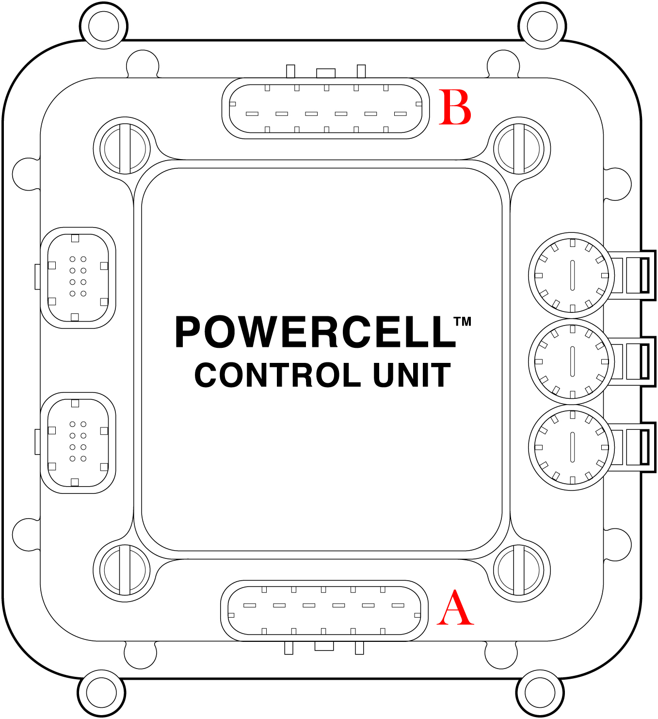
 Copyright Infinitybox, LLC 2021. All Rights Reserved.