Posts

Wiring Russ Thompson Turn Signal System

Russ Thompson has been making high-quality turn signal assemblies for the full range of Factory Five Cars.  We have been getting a lot of requests for a wiring diagram to show you how to connect his turn-signal switch to our new Infinitybox IPM1 kit.  This blog post will get you those details.  Please note that this post details the wiring using our Next Generation System.  Please click here if you have one of our Legacy Infinitybox systems.

Russ Thompson made high-quality turn signal stalk assemblies for the Factory Five Roadster, Type 63 and the GTM.  You can learn more about his products at this link.

The new Infinitybox IPM1 kit includes the next generation of our MASTERCELL and POWERCELLs.  These products include numerous refinements and enhancements that our customers have requested.  You can learn more about the IPM1 kit at this link.  Turn signals and 4-way flashers have always been easy to wire with the Infinitybox system.  The addition of indicator outputs on the MASTERCELL NGX make this even easier.

The Infinitybox manages all the required functions for turn signals and 4-ways.  The MASTERCELL handles the patterns internally so you do not need a flasher relay.  You simply ground the inputs for the left and right turn signals to make them work.  We manage the rest for you.  The distributed architecture of the system makes running the wire through your car easy.  You have a POWERCELL output module in the front of your car and one in the rear.  Each of these POWERCELLs has outputs for turn signals.  That means that you are running the front turn signals from the front POWERCELL and the rear signals from the rear.  All of your wire is run locally.  This minimizes the total amount of wire needed in the car.

We also manage the 4-ways or hazards internally.  The MASTERCELL generates the pattern so no external flasher is required.  When you ground the input for the 4-ways, the MASTERCELL tells the front & rear POWERCELLs to flash all the turn signals together.

Wiring the turn signal switch and the hazard switch is very easy with the Infinitybox IPM1 kit.  You simply connect the left turn, right turn and 4-way inputs from the MASTERCELL to the switches in the Russ Thompson turn signal stalk.  Instead of connecting the other side of the switch to a flasher, you connect it to ground.  When you turn on a switch, that pulls the MASTERCELL input to ground, which triggers its function.  The following diagram shows how to connect the inputs to the stalk switches.

Picture of Infinitybox wiring diagram showing how to wire Russ Thompson Turn Signal Stalk

Picture of Infinitybox wiring diagram showing how to wire Russ Thompson Turn Signal Stalk

The wire colors for your MASTERCELL inputs are defined in the configuration sheet that came with your kit.  Click on this link to get to our standard front-engine configuration.

For the turn signal wires from the stalk, the black-red wire should connect to ground.  The red-white wire connects to the MASTERCELL input for your left turn signal and the red-yellow wire connects to the input for the right turn signal.

There is another great feature included with our MASTERCELL NGX.  In addition to the inputs, the MASTERCELL NGX has outputs to locally power things like indicators.  Since your MASTERCELL is located close to your switches, it is very easy to run these indicator wires to the indicator lights on your dash for your turn signals and indicators.  When the MASTERCELL is telling the POWERCELLs to flash the turn signals, it is also flashing the indicators.  See the wiring diagram above for details on wiring you dash indicators.

The last feature in the Russ Thompson kit is the button at the end of the turn signal stalk.  This is a momentary button intended to be used to control the high-beams.  With a typical wiring set up, you would need a separate relay or high-beam module to manage this.  With the Infinitybox IPM1 kit, you can control your high-beams from this momentary button internally.  Our high-beam input can be set to toggle the high-beams on and off.  See the diagram above to show how to wire this input to the switch in the Russ Thompson kit.  Both the wires for the button on the Russ Thompson harness are black.  Connect one to ground and the other to the MASTERCELL input for the high-beams.

You can also use this button to control the horn if you want.  Instead of the high-beam input, connect the horn input.  See you configuration sheet for details.

You can download a PDF version of this wiring diagram by clicking this link.

Contact our technical support team if you have any questions about wiring your Factory Five car using our Infinitybox IPM1 kit and the Russ Thompson turn signal stalk kit.

Floor dimmer switch

Floor Mounted Dimmer Switch

When it comes to controlling lights with our Infinitybox system, you have many different options.  This is especially true for your headlights and high-beams.  You can see earlier blog posts about wiring headlights and high-beams by clicking these links.  In most cases, you are going to use the headlight and high-beam outputs on the front POWERCELL.  These are controlled by their own inputs connected to different switches on your dash or the steering column.  You can also use a floor-mounted headlight dimmer switch to switch between the headlights and high-beams in your car.  This blog post will show you the details.

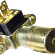
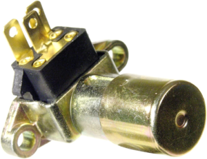
The floor dimmer switch is designed to toggle between the headlights and high-beams.  The headlight switch brought power to a common terminal on the switch.  The headlights and the high-beams wired to their respective output terminals on the switch.  When you turn on the headlight switch, power is applied to the dimmer switch on the floor.  Pressing this switch with your foot toggles between the headlights and high-beams.  When you turn off the headlight switch, there is no power at the switch so your headlights and high-beams turn off.

Floor dimmer switch

Picture of a floor headlight dimmer switch

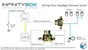
Wiring a floor dimmer switch is simple with the Infinitybox system.  First, you are going to wire your headlight switch to the headlight input going to the MASTERCELL.  Remember that the MASTERCELL inputs are ground switched.  When the headlight input is switched to ground, the MASTERCELL will tell the front POWERCELL to turn on the output for the headlights.  We have many different wiring diagrams showing different how to wire different headlight switches in the Resources section of our website.  This link will take you to the wiring details for the most common GM-style headlight switch.

If you are going to use a dimmer switch on floor to switch between headlights and high-beams, you will not need to use the high-beam output on your front POWERCELL.  This opens up this output to be used for other accessories or auxiliary functions.

Next, you are going to connect the headlight output from your front POWERCELL to the common terminal on your dimmer switch.  In most cases, this is the center terminal on the switch.  It may also be labeled as “From Headlight Switch”.  Check the wiring diagram for your specific switch.

Next, you are going to connect the output terminals from your dimmer switch to your headlight bulbs and high-beam bulbs.  The terminals on your switch should be labeled for the headlights and high-beams.  Check the wiring diagram for your specific switch for more details.

Lastly, you can tap off the high-beam terminal on the dimmer switch with a wire for the high-beam indicator on your dash.

This wiring diagram shows the connection from the MASTERCELL to the headlight switch, the headlight output from the POWERCELL to the dimmer switch, the connections from the dimmer switch to the headlights & high-beams and the connection for the high-beam indicator on the dash.

Floor dimmer switch wiring diagram image

Picture showing wiring diagram for a floor mounted headlight dimmer switch.

You can download a PDF version of this wiring diagram by clicking this link.

Reach out to our team if you have any questions about wiring a floor dimmer switch to control your headlights and high-beams with the Infinitybox system.  You can call us at (847) 232-1991 or click on this link to contact our team directly.