Lucas Switch
There are very few companies in the car world that get the ribbing of Lucas Industries. They are the butt of many an old car guy’s jokes about reliably, safety and burning. The company was founded in the 1860’s in the UK and produced electrical components for over 100 years for all of the popular British brands. These include MG, Austin, Cooper, Jaguar and even the ubiquitous Cobras built by Shelby. It is not uncommon to hear of them referred to as “Lucifer” because of their alleged history of causing vehicle fires. One of the benefits of our Infinitybox system is that you can use practically any switch to control things in your car. This includes a period correct Lucas switch in your restoration of a MG or a Cobra replica build. Read below how to connect the Lucas 31788 headlight switch into the inputs on your Infinitybox MASTERCELL.
Our Infinitybox system has been used to wire some of the most advanced resto-mods and Pro-Touring builds. At the same time, our customers use our system in a lot of classic restorations and component car builds. The most popular component car that we see from our customers is the MK4 Roadster from Factory Five. This is a great replica of the Cobra made famous by Carroll Shelby. A lot of guys want to build this car and customize it to make it unique to them. Other guys want to build it period correct to look like the original Cobras but with all modern systems under the skin.
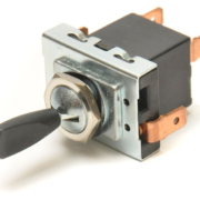
We got a question this week from one of our customers building a Factory Five Cobra. He wants to use the original headlight switch from Lucas in the car and wanted to know how to wire it to the MASTERCELL inputs. He’s using the Lucas 31788 switch. That’s an easy thing to do.
One of the advantages of our system is that it takes very little current to turn on a MASTERCELL input. The actual amount is less than 1 milli-amp. (0.001 Amperes). This means that you don’t have to use high-current switches to turn your lights, fans, ignition or starter solenoid on or off. The high-current part of the circuit is managed in the POWERCELL. A lot of the alleged issues that Lucas had over the years came from too much current being pushed through their switches. Our MASTERCELL completely eliminates that.
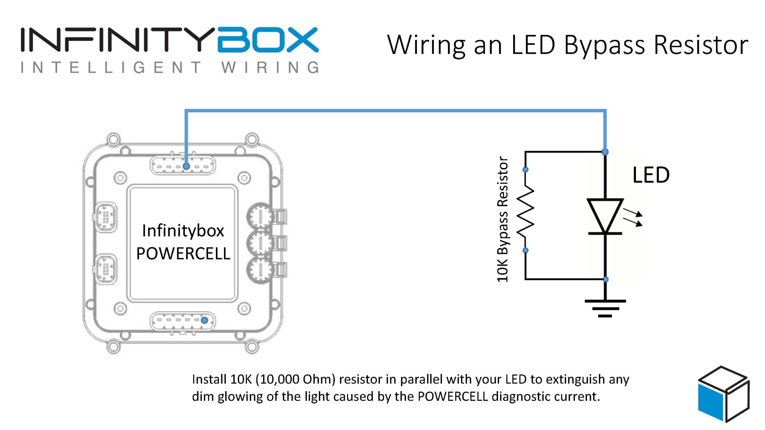
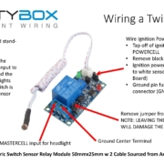
This diagram shows you the specifics on how to wire the MASTERCELL inputs for parking lights and head lights to the Lucas switch.
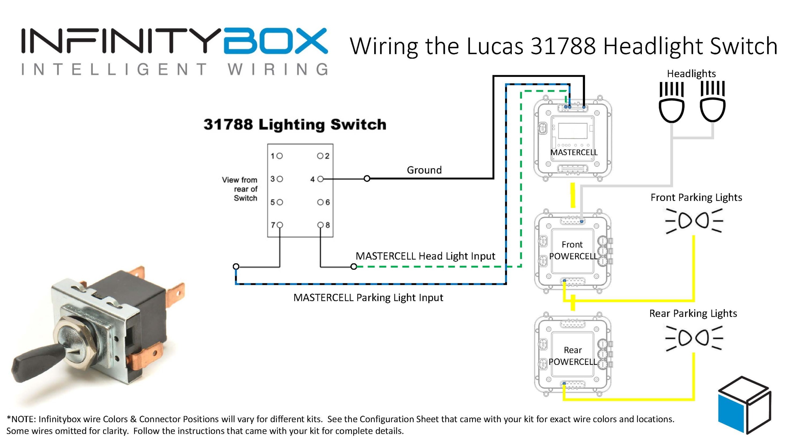
Picture of Infinitybox wiring diagram showing how to control headlights and parking lights from a Lucas Switch
Terminal 4 on the switch needs to get connected to ground. If you understand how the switch works, this may seem counter-intuitive, just trust us. You can either connect this terminal directly to the chassis or use one of the black ground wires that is included in the MASTERCELL inputs harness. Using one of the dedicated ground wires is our preferred way of wiring these kinds of switches.
From there, connect the MASTERCELL input for the parking lights to terminal 7 and the input for the head lights to terminal 8. The switch is set up internally so that the parking lights will stay connected when the switch is in the headlight position.
Check the specific configuration sheet that came with your kit for the exact wire colors and connector locations for these inputs. Different configurations may have different wire colors and connector locations.
You can read these blog posts to get more details about wiring the head lights and parking lights to the POWERCELL outputs.
That’s all you need to do to wire your headlights and parking lights to this Lucas switch. When you turn on the parking lights or the headlights, the MASTERCELL will see the switch turn on and send the appropriate commands to the front & rear POWERCELLs to manage the lights.
You can download a PDF copy of this wiring diagram by clicking this link. If you have any other specific technical questions, you can contact one of our technical support engineers by clicking this link.
 Copyright Infinitybox, LLC 2021. All Rights Reserved.
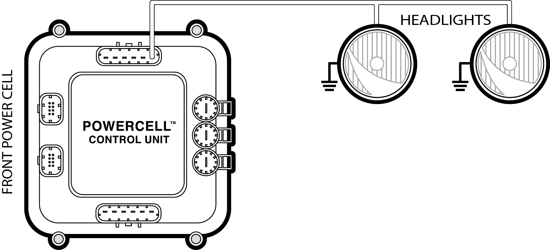
 Copyright Infinitybox, LLC 2021. All Rights Reserved.