
Headlight Switch
It’s time to wire in the headlight switch in our customer’s 1967 Mustang. They are installing our 20-Circuit Kit in the car. In previous posts, we blogged about wiring the headlights and parking lights to the outputs on the POWERCELLs in the car. You can read about that process at this link.
Remember that there is no direct connection between your switches and the things that you are switching. In this case, there is no direct connection between the headlight switch and the headlight bulbs in the front of the car. The headlight switch connects to the MASTERCELL. The headlight bulbs connect to the POWERCELL. The MASTERCELL and POWERCELLs are connected with our CAN data cable. When you turn on the headlight switch, the MASTERCELL sees the switch turn on. It sends a command to the POWERCELL in the front of the car and commands it to turn the output on that powers the headlight bulbs. The same thing happens when you turn on your parking lights. The MASTERCELL sees the parking light switch turn on. It sends a command to the POWERCELLs in the front and rear of the car. Each of these POWERCELLs turn on parking light outputs locally in the car.
Our customer started with the original headlight switch that came with the car. After some checking and testing of the switch, they figured out that the switch was bad. Something inside the switch failed.

Picture showing how to use a multimeter to check continuity between terminals on a headlight switch
They wanted to keep the traditional pull-type headlight switch in the car so they picked up a replacement switch made by Standard Motor Products. This what the switch looks like.
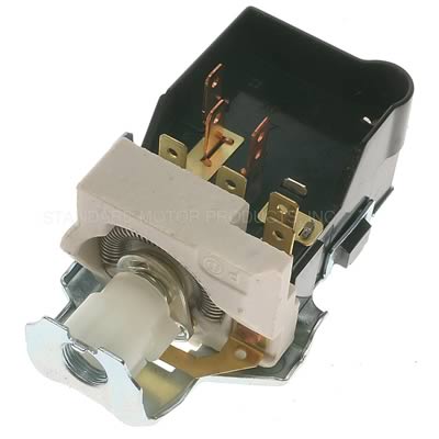
Picture of a headlight switch manufactured by Standard Motor Products
This is a multi-function switch. It controls the parking and headlights in the car. You get the parking lights when you pull the switch to the first detent. You get both the parking lights and headlights when you pull the switch to the second position.
This is a very common switch, used in lots of different cars. We created a specific wiring diagram showing how to wire your MASTERCELL inputs to the terminals on the switch. This picture shows you the diagram.
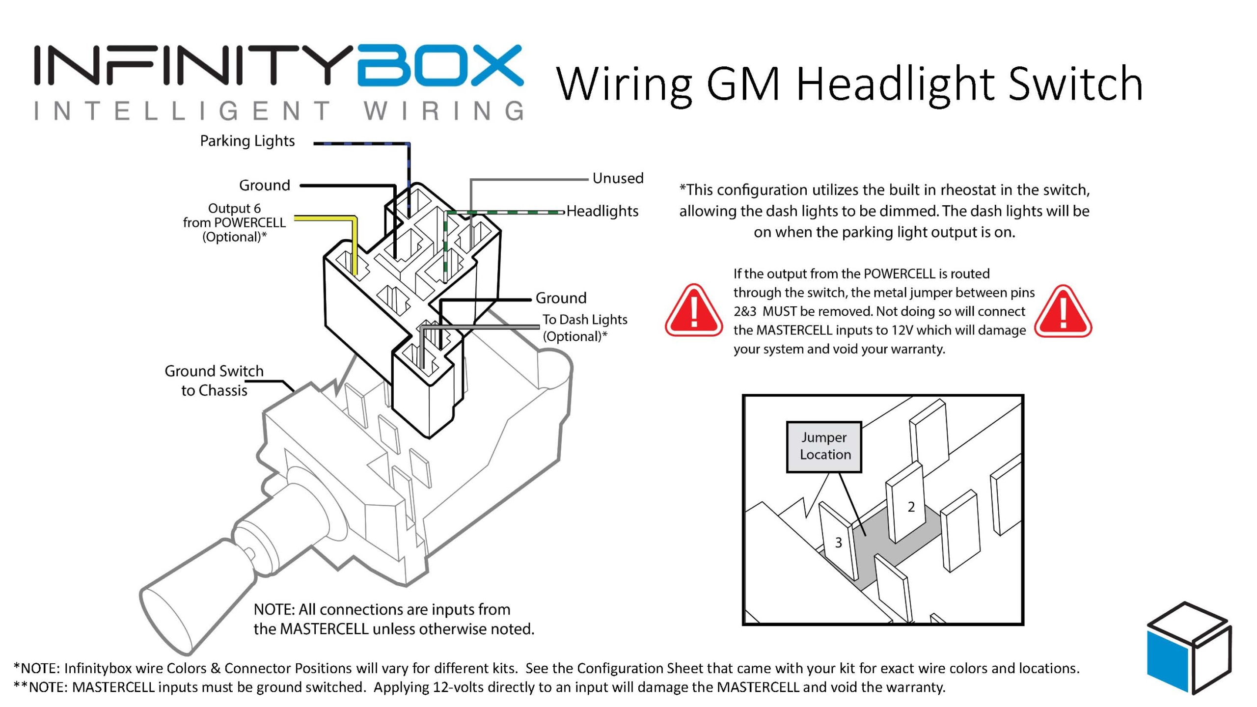
Picture of a wiring diagram for a typical headlight switch
You can download a PDF of this diagram by clicking this link.
The first thing that we did was to check the configuration sheet for this system. You can get more details on the configuration sheet for your system by clicking this link. The MASTERCELL inputs for the headlights and parking lights are going to connect to the switch. The headlight input is the white wire with the green tracer. The parking light input is the blue wire with the black tracer. Both of these inputs are on the MASTERCELL input harness. You also need three ground connections to this switch. Two of the terminals need to be grounded and the switch housing needs to be connected to ground. You can use the black wires that came in the MASTERCELL input harness as grounds for this switch. One of the MASTERCELL ground wires can handle the ground for the entire switch. Just jumper that black wire between the different terminals on the switch and the case.
Follow the diagram to see which terminals on the headlight switch connect to the headlight and parking light input wires on the MASTERCELL. This is pretty simple.
Once you have the input wires connected and the grounds connected, you have wired the inputs for the headlights and parking lights. When you pull the switch to the first position, the switch connects the parking light input wire to ground. This sends the signal to the MASTERCELL to control the lights through the front and rear POWERCELLs. When you pull the switch to the second position, the switch connects the headlight input to ground. This triggers the MASTERCELL to control the headlights from the front POWERCELL. When the switch is in the headlight position, the switch also keeps the parking light input connected to ground.
Once you have the headlight and parking light inputs wired, you can also use this switch to control and dim your dash lights. This specific switch has a rheostat built in to dim dash lights. In most cases, you are powering your dash lights off of your parking light output. See this blog post for more details. You will have power to your dash lights when the parking lights or headlights are on from this switch.
This switch has a rheostat built in to dim the dash lights. A rheostat is a variable resistor. Turning the knob, increases or decreases the resistance in series with the dash lights. This lets more or less current flow to the dash lights, which will dim or brighten them. Please note that the dimming effect may not be as significant when using LED dash lights.
You can wire the dash light feed though the rheostat on the headlight switch. See the wiring diagram above for the details of which terminals need to connect to the wires. Please note that there is a metal jumper that must be cut to do this. If you do not remove this metal jumper, you will damage your MASTERCELL inputs and potentially void the warranty.
That’s it. This one post covers wiring your parking light input, your headlight and your dash lights. Please click this link to contact our team with any questions about our Infinitybox system.