Posts

NGX Configuration Sheet- POWERCELL Outputs

We have completely re-engineered our Infinitybox system to bring the latest in wiring and body control technology to anyone wiring a hot rod, street rod, resto-mod, kit car, race car or Pro-Touring build.  We have also re-engineered the NGX configuration sheet for this system.  This new configuration sheet format makes it easier to read, gives more detail and gives all of the wire colors needed to connect to your switches and your accessories in your car or truck.  This is the standard configuration that comes loaded on all new IPM1 kits.  With our inCODE NGX programming tool, you can modify this configuration to meet the needs of your unique project.

This link will take you to the Front Engine configuration for our IPM1 kit.  Watch the resources section of our website for other setups including the Rear Engine configuration.  This blog post will walk through the details for the POWERCELL output assignments and the outputs on the MASTERCELL NGX.  Watch out blog for details on the inMOTION NGX inputs and outputs.

To start, the configuration sheet is broken down into the different cells in the Infinitybox NGX system.  This includes the front & rear POWERCELLs and the different inMOTION NGX cells for the doors (driver, passenger, driver rear & passenger rear).  Our IPM1 kit comes standard with one MASTERCELL NGX and two of our POWERCELL NGXs.  You can add as many inMOTION NGX door modules as you need for your car or truck.  Most customers will add 2 or 4 inMOTION MGX modules to their system as accessories depending on if they are working on a 2 or 4 door car.  Since the MASTERCELL NGX has low-current outputs to drive indicators on the dash, we added a page that details the wiring for these.  Lastly, we added pages that detail all the wires in the MASTERCELL A & B connector harnesses.

For the front & rear POWERCELL pages, we’ve reorganized the columns to make this easier to read.  The first column lists the function assigned to each POWERCELL output.  This includes things like turn signals, ignition, starter solenoid, lights, cooling fans and fuel pumps.  Any output that is labeled as OPEN is an auxiliary.  There is no set function assigned to the output.  Its corresponding input will turn it on and off.

The next column gives the address of the POWERCELL.  By default, the front POWERCELL is addressed as 1 and the rear POWERCELL is addressed as 2.

The next column lists the POWERCELL output by number for the function.  There are 10 outputs on a POWERCELL and they are listed in numerical order.  Some functions list multiple outputs.  Examples include the 4-ways and the One-Button Start.  In these cases, the function uses two different outputs.  The 4-ways use the left and right turn signal outputs.  The One-Button Start function uses the outputs for both the ignition and starter.

The next column gives you the POWERCELL output connector that the output is connected to.  The manual for your IPM1 kit has a diagram that identifies the A & B output connectors on the POWERCELL.  Please pay attention to this diagram carefully.  The A & B connectors are interchangeable on the POWERCELL.

The next column defines the “personality” assigned to the POWERCELL output and its corresponding input.  The personality is how the output behaves when it is turned on.  The most basic and common personality is “track”.  Outputs assigned the track personality turn on when the input is turned on and turn off when the input is turned off.  The input tracks the state of its input.  You can learn more about the other available personalities by clicking this link.

The next column lists the wire color for each output on the POWERCELL output harness.  Please note that the output harness colors for the outputs are the same for the front and rear POWERCELLs.  Pay attention to the POWERCELL address to make sure you are connecting to the right output.

The last three columns tell you the details for the MASTERCELL inputs that are controlling each POWERCELL output.  The input number, the MASTERCELL connector (A or B) and the wire color are listed.

After the POWERCELL details, the next page details the low-current outputs on the MASTERCELL NGX.  These outputs give you easy access to low-current outputs to drive indicators on your dash.  There are 8 of these outputs.  The first 4 are assigned to the left-turn signal indicator, the right-turn signal indicator, the high-beam indicator and the illumination for your gauges.  The next 4 are auxiliary outputs and can be set up as an advanced feature of the MASTERCELL NGX.  Contact our tech support team for details.

Watch the blog for more details on our new configuration sheet format and the details for the inMOTION NGX.  Click here to contact our tech support team with any questions.


Setting Infinitybox Address Jumpers

Our Infinitybox system is very flexible.  You can scale it from a very simple wiring system to one that is very complicated.  Our standard 20-Circuit Kit includes one MASTERCELL and two POWERCELLs.  You can add more POWERCELLs to expand the number of outputs in your system.  Every POWERCELL you add gives you 10 more outputs.  You can also add the inMOTION cell to control things like your power windows and power locks.  For all of these cells to work correctly on our Infinitybox CAN network, they each need their own address.  This is a unique name given to each cell so that it knows who it is and what commands it should listen to.  This blog post is going to go through setting the Infinitybox address jumpers.

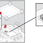
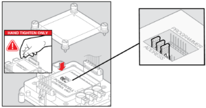
There are address jumpers located under the clear covers of the POWERCELL and the inMOTION cell.  Setting the Infinitybox address jumpers is done in exactly the same way for both the POWERCELL and inMOTION.  The following illustration shows where the address jumpers are located under the POWERCELL cover.

POWERCELL Address Settings

POWERCELL Address Settings

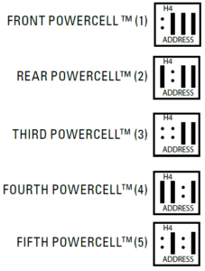
The cells use BCD to set their address.  With BCD, you can use a small number of pins to set a large number of options.  In the case of our POWERCELLs and inMOTION cells, there are 4 sets of pins.  Each of these pins has a numerical value.  Going from left to right, these pins are 1, 2, 4 and 8.  When the cell power up, it looks at those pins to get its address.  It adds up the value of the pins that do not have a jumper on them.  For example, if there was no jumper on the first set of pins, that would be a value of 1.  If there was no number on the second set of pins, that would be a value of 2.  If there were no jumpers on the first and second set of pins, that would be a value of 3 (1 + 2).  The follow illustration shows the combinations of jumpers to get the most popular addresses used with our Infinitybox system.

How to set the address jumpers on the Infinitybox POWERCELL

How to set the address jumpers on the Infinitybox POWERCELL

In all standard 20-Circuit Kits.  The front POWERCELL is addressed as 1 and the rear POWERCELL is addressed as 2.  If you add inMOTION, that is addressed as 3.

The cells only learn their address the instant they are powered up.  If you change the address while the system is powered up, the cells will not change their address.  You should disconnect power from the system before you change any address headers.

When you are first setting up your 20-Circuit Kit.  You need to make sure that you have the POWERCELL jumpers set to the correct addresses for their location in your car.

Click on this link if you have any additional questions about setting the Infinitybox address jumpers.

Fixing inCODE Software Driver

Our inCODE Programmer is the tool that you need to load custom configurations into your Infinitybox system.  It connects your computer to your MASTERCELL to let you make changes.  Our technical support team makes the changes for you.  You use inCODE to load these changes into your system.  This link will take you to the basics on using inCODE.

If you carefully read the instructions for using inCODE, you will see a big and bold message that says to not plug the inCODE programmer into your computer until after you have loaded the Embed Inc software.  When you plug the inCODE programmer into your computer, Windows automatically installs the drivers that it needs to make it work correctly.  When you install the Embed Inc software, it installs the drivers for inCODE and leaves instructions for Windows so it knows what to do with inCODE.  If you plug inCODE into your computer before you install the Embed Inc software, your computer takes a guess at what the inCODE programmer is and assigns a random driver to it.  You will get an error when you try to load code onto your system if this happens.

Reinstalling the Embed Inc software will not solve this issue since Windows has already assigned the wrong driver to the inCODE hardware.  You need to remove the inCODE programmer from your Device Manager and let Windows recognize it again.  This quick video will help you go through this process.

Please click on this link to contact our technical support team if you have any additional questions about setting up your inCODE programmer.


Updating inTOUCH NET

Our inTOUCH NET product completely changed the way that our customers interact with their vehicles and the Infinitybox system.  They have a universal interface that is fast, responsive and flexible plus it doesn’t require any custom apps.  Their vehicle can be controlled from Apple, Android and Windows smart devices with ease.

Just like the rest of the Infinitybox hardware, inTOUCH NET can be updated in the field using code that we create for you.  Give our technical support team a call with the changes that you need for your inTOUCH NET and we will email you the files necessary to implement the changes.

PLEASE NOTE: YOU WILL ONLY HAVE TO GO THROUGH THESE STEPS IF YOU ARE DIRECTED TO DO SO BY AN INFINITYBOX TECHNICAL SUPPORT REPRESENTATIVE!

inTOUCH NET uses very sophisticated micro-controllers to do its job.  This process sounds complicated but it is easier than it seems.

Here are the steps that you need to follow to update your inTOUCH NET system.

  1. You will receive an email from Infinitybox technical support with the updated files that are specific to your inTOUCH NET.  Download these files and save them to a convenient location on your computer.
  2. Disconnect inTOUCH NET from your Infinitybox system.
  3. Download and install  http://ww1.microchip.com/downloads/en/DeviceDoc/MPLAB_IDE_8_92.zip on your computer.
  4. After it is successfully installed, reboot your computer.
  5. After the computer is rebooted, plug the USB cable from inTOUCH NET into your computer.  Let it load the drivers.  inTOUCH NET is getting its power from the USB connection for this process.
  6. Launch the MPLAB IDE software.
  7. Go to Configure/Select Device.  Select PIC32MX795F512L from the Device drop down menu.  Then hit OK.
  8. Go to Debugger/Select Tool and choose 10 PIC32 Starter Kit.
  9. Go to File/Import and choose the file with the name that ends in .hex.
  10. To go Debugger/Programming/Program All Memories.  It should take about 5 seconds.  You will get a message on the screen that says programming successful.
  11. Go to Debugger/Select Tool and None.
  12. Close the MPLAB IDE software.
  13. Connect to the inTOUCH NET server using the Wi-Fi on your laptop.  Used the SSID and password that came with your kit.
  14. Launch Google Chrome or Firefox.  Internet Explorer will not work for this step.
  15. Navigate to 192.168.1.50/mpfsupload.
  16. Hit the browse button that appears on the screen.  Select the file with the name that ends in .bin.
  17. Press the upload button.  You will get a message on the screen that confirms that the website was loaded to inTOUCH NET.
  18. Unplug inTOUCH NET from the USB port on your computer.
  19. Connect inTOUCH NET to the Infinitybox system.  Shut down all power and start up again.  Wait 30 seconds for the server to initialize.
  20. Connect to the inTOUCH NET network with your smart device.
  21. Browse to 192.168.1.50.
  22. The initial password to get past security is 123 [ENTER].

Your system is now updated with your new code.

If you have any questions with these steps, give our team a call at (847) 232-1991 or email us at sales@infinitybox.com.  You can also contact our team directly by clicking this link.  

Updating with inCODE

Updating with inCODE is very simple but there are two very important warnings that you must understand before you go any further.

***DO NOT PLUG THE inCODE PROGRAMMER INTO YOUR COMPUTER UNTIL YOU HAVE INSTALLED THE SOFTWARE PER THE INSTRUCTIONS BELOW***

…and…

***PAY ATTENTION TO WHICH CELLS YOU ARE UPDATING.  IF YOU RECEIVED A FILE TO UPDATE YOUR MASTERCELL, ONLY LOAD THAT ON A MASTERCELL.  IF YOU RECEIVED A FILE FOR YOUR POWERCELLS, ONLY LOAD THAT CODE ON YOUR POWERCELL.***

That being said, let’s take a look at the steps for updating with inCODE.

One of the advantages of our Infinitybox system is the ability to load new configurations to it in the field.  This video goes through the process of updating your Infinitybox MASTERCELL.

***DO NOT PLUG THE inCODE PROGRAMMER INTO YOUR COMPUTER UNTIL YOU HAVE INSTALLED THE SOFTWARE PER THE INSTRUCTIONS BELOW***

Here are the instructions to load the software and update your system using the inCODE programmer.  This will work for any Windows operating system running at 32-bits or 64-bits.  Please note that there is no application that will work for Apple or Mac.  Also, this must be done from a PC or a laptop.  You cannot use a tablet to run inCODE.  Contact Infinitybox technical support to get a link to download the software to run the inCODE.  You can contact our team by clicking this link.

  1. Temporarily disable your virus scanning software.
  2. Download the software application from the link provided to you from Infinitybox technical support.
  3. Run the install_picprg executable.
  4. When the installation is done, plug the programmer into the computer.  Let it find the drivers as necessary.
  5. Reboot the computer.
  6. Go to Programs/Embed Inc/Program PIC.
  7. Save your hex file to your desk top.
  8. UNPLUG ALL CONNECTORS FROM THE CELL BEFORE YOU PLUG THE inCODE PROGRAMMER INTO IT.
  9. Plug the programmer header into the cell to be updated.  Follow the instructions that came from Infinitybox technical support carefully.  Loading code on the wrong type of cell can cause severe damage to the system.  For example, programming a POWERCELL with MASTERCELL code will cause damage to the cell.
  10. Browse for the file and hit PROGRAM on the GUI.

The programming window looks like this:

Picture of the inCODE Graphical User Interface

Picture of the inCODE Graphical User Interface

When completed, unplug the inCODE programmer from the cell and plug the harness connectors back in.

PLEASE NOTE:  You may get a warning from your anti-virus software about the inCODE download.  It depends on the browser and the anti-virus software that you are using.  We test this software frequently and know that it is safe.  Contact our technical support team with questions about this.

If you plug the inCODE programmer into your computer before you install its software, Windows will randomly assign a driver to it.  The inCODE programmer will not work correctly when you install the software.  To fix this, please follow these instructions by clicking this link.

One last note, depending on how your version of Windows is installed and your administrator permissions, the Embed, Inc. installer may not put the executable icon on the desktop.  If you cannot find the icon to launch Pic_Prog use File Explorer to get to the C: drive on your computer.  In the root of the C: drive, click on the folder labeled “embedinc”.  Then click on the folder labeled “com”.  You will find a file called “pic_prog_w.exe” in the “com” folder.  Double click on this file to launch the Pic_Prog application.

Please contact our technical support team by clicking this link if you have questions.