 Copyright Infinitybox, LLC 2021. All Rights Reserved.
 Ignition
In our last post, we talked about wiring the starter solenoid to the POWERCELL in your 20-Circuit Kit. Now it is time to wire the ignition. There is a dedicated output on your POWERCELL that supplies battery voltage for your ignition. This is your “key-on” power. In this post, we are going to talk about wiring the POWERCELL output. We’ll discuss wiring the MASTERCELL input to the ignition switch in later posts.
Our Infinitybox system can power any type of ignition system. It can be a basic set of points or a highly sophisticated EFI system. In either case, we are going to power the ignition system when the key is on. In the case of this 1967 Mustang, the customer is using the Ford Coyote Crate Motor with the Ford ECU.
Check the configuration sheet that came with your kit. It will define which output is for the ignition. In most cases, it is the light-green wire on the front POWERCELL. This is output 3 on the B connector.
You need to carefully read the instructions for your ignition system. In most cases, there will be a wire that needs to connect directly to the battery to give it constant 12-volt power. There will also be a key-on or ignition power feed. That will come from the light-green wire on your POWERCELL. Over the years, we have accumulated many different wiring diagrams for different ignition systems. They can be found in posts on our blog or in our reference library. We’ll highlight some of the most popular in this post.
The most common ignition system that we see customers using is a ignition box from MSD. The MSD 6A or 6AL are some of the most popular. There is a heavy red and heavy black wire in their harness. These wires need to connect directly to the battery and to chassis ground, respectively. Then there is a lighter gauge red wire that is for the key-on power. This will connect to the ignition output on your POWERCELL. See the picture below for more details.

Image of wiring diagram showing how to wire the MSD 6A with the Infinitybox system.
We also have many different posts that talk about how to wire the ignition outputs to EFI systems. This picture shows wiring our ignition outputs to the FAST EZ-EFI system.

Picture of wiring diagram showing how to wire the FAST EZ-EFI fuel injection system with the Infinitybox system.
Our ignition output from the POWERCELL connects to the pink wire in the EZ-EFI harness. You can read the entire blog post on the FAST wiring at this link.
Another popular option for our customers is the Holley Dominator EFI system. This link shows you a picture of how to wire that into our system.

Image of wiring diagram showing how to wire the Holley Dominator EFI System with the Infinitybox System.
In the case of our customer’s 1967 Mustang, they are using the Ford Coyote crate engine for this car. We have a complete schematic that shows you how to connect the ignition output from the POWERCELL to the ECU. You can see that schematic at this link.
Once you have your ignition system or EFI system wired to the ignition output, you also have to think about the other things that you want to come on with your ignition switch. Remember that each POWERCELL output has the capacity of 25-amps. You can use this single output to power many different functions. You are going to use this same ignition output to power your gauges, your transmission controller, your radio power or any other function that you need to power with ignition.
In earlier posts in this series, we talked about how to splice off of POWERCELL outputs for multiple taps. These examples included your headlights, high-beams and parking lights. For your ignition, we recommend creating a ignition bus that you can use to power the many different switched functions in your car. You can use a terminal strip to create a common point for your ignition functions.
You can purchase terminal strips like this from companies like Del City and Waytek Wire. Make sure that you pick a terminal strip that has an insulating cover on it. You want to make sure that you protect these wires from getting shorted to ground.
Another option is to use our Infinitybox Splice Saver Kit. This is a simple accessory that makes connecting a POWERCELL output to multiple wires robust and reliable. This picture shows you how you can use the Splice Saver Kit to create a sealed junction point for everything that needs to get powered off of your ignition.
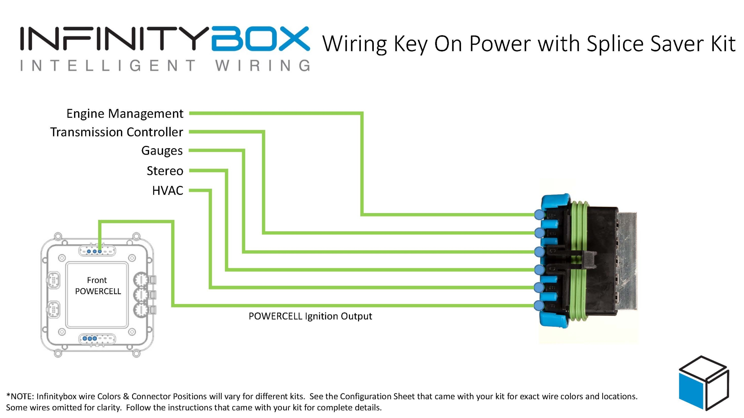
Wiring ignition key-on power with the Infinitybox Splice Saver Kit
Please contact us with questions about wiring the ignition output on your Infinitybox system. Click this link to reach out to a member of our team.