+12 Volt Brake Light Signals
Our MASTERCELL uses ground switching to control all of the electrical functions in your car. There are many advantages to ground switching. You need less wire, you are only triggering a signal so the there is less current flowing through the switch and you can get the ability for combinational logic easily. This link will take you to a good description of how the MASTERCELL inputs work and how you should wire the switches connected to your Infinitybox system. Your brake pedal switch is no different. You run your MASTERCELL input for your brake lights to the switch on the pedal. You connect your brake lights to the outputs on your rear POWERCELL. When you step on the pedal, the MASTERCELL tells the rear POWERCELL to turn on the brake lights. It’s pretty simple. This blog post will get you more details on wiring your brake lights. Normally, you’re going to use ground switching between your brake pedal switch and your MASTERCELL. There are some times when you need a positive 12-volt signal from your brake pedal to interface with other electrical systems. This blog post is going to show you a few easy options to get this +12 volt brake light signal.
There are several external electrical systems that need a positive signal from the brake pedal. Examples of these systems include transmission controllers to manage the torque converter lock up. Other examples include cruise control systems to disengage the system when you step on the brakes. Another example is an external PKE system with one button start. You must step on the brake pedal to safely start the car. In a typical Infinitybox wiring set up, there is no battery voltage at the brake pedal switch. An option to get this +12-volt signal would be to tap off the brake light on the rear POWERCELL. This requires that you run a wire from the back of the car up to the front. This may also be an issue if you’re using out 1-filament brake light set up. We’re going to give you a few simple options to get this +12 volt brake light signal from the pedal to keep the wiring in your car short.
Before we get too far, you need to carefully read and understand the instructions for the electrical system that you’re interfacing with your Infinitybox system. Make sure you know exactly what signal you need from your brake pedal switch. Some systems need a +12-volt signal when you step on the brakes and a ground signal when your foot is off the pedal. Other systems need a 12-volt signal when you’re foot is off the pedal and ground when you step on the pedal. Make sure you understand what you need. The following examples will show you how to accommodate any of these options.
The next thing that we need to review is the difference between Normally Open and Normally Closed switches. These designations describe what the contacts in the switches are doing when the switch is in its normal state. A Normally Open (NO) switch is off when you are not pushing it. You have to push the switch to turn the switch on. A Normally Closed (NC) switch is on when you are not pushing it and off when you push it. The majority of the switches in your car are Normally Open (NO) but there are a few exceptions.
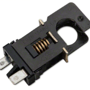
There are a few different types of brake pedal switches. Two terminal switches are the most common. There are also 4-terminal switches. Within the 4-terminal switches, most of these have a set of Normally Open (NO) contacts and a set of Normally Closed (NC) contacts.
Let’s start with the 2-terminal switches. These have a set of Normally Open contacts. The switch is off when you are not pressing the brake pedal. When you step on the pedal, you close the contacts. This makes an electrical connection between the two terminals on the switch. In a normal Infinitybox set up, you ground one of the terminals on the switch and connect the second terminal to the MASTERCELL input for your brake lights. When you step on the brake pedal, you make an electrical connection between the MASTERCELL input and ground. This is a very simple set up, however you don’t have +12 volts at the switch.
This diagram shows you how to wire your 2-terminal brake pedal switch to get a +12 volt signal and a ground signal for the MASTERCELL. It uses an Infinitybox inVERT Mini to flip the 12-volt signal from the switch to ground the MASTERCELL input.
Instead of grounding one terminal on the brake pedal switch, connect it to the ignition output on your front POWERCELL. When the ignition is on in the car, you will have voltage on this terminal on the switch. You can splice into the ignition output wire on the POWERCELL or you can use one of our Infinitybox Splice Saver kits to make this connection. You will then connect the second terminal on the brake pedal switch to your controller that needs the +12-volt signal when you step on the pedal. On this second terminal, you will also connect the input wire for the inVERT Mini. The black wire on the inVERT Mini gets connected to ground and the output wire connects to the MASTERCELL input for your brake lights. It’s pretty simple. You can download a PDF copy of this wiring diagram by clicking this link.
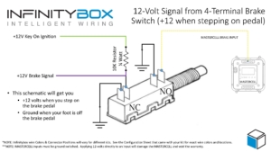
Another option is if you have a 4-terminal brake pedal switch. These have two pairs of terminals. Usually, the pair of terminals closest to the switch plunger are the Normally Open contacts. They close when you step on the brake pedal. The set of terminals furthest from the plunger is Normally Closed. These contacts open when you step on the brake lights. These diagrams assume that your switch has a Normally Open and a Normally Closed set of contacts. Please confirm the type of switch that you have by checking resistance between the terminals with a multimeter. You are going to use the Normally Open terminals to ground your MASTERCELL input for the brake lights. Ground one of these terminals and connect the second terminal to the MASTERCELL input.
On the Normally Closed set of terminals, you are going to connect one of these to ground. You then connect one end of a 10K (10,000 ohm) resistor to the second Normally Closed terminal. The other end of the resistor should get connected to the ignition output on your front POWERCELL. This resistor should be rated for at least 1/4 (0.25) Watts. You can buy these easily from Amazon. Just search for “1/4 watt 10k resistor”. This picture will show you the connections that you need to make to your brake pedal switch.
When you are not stepping on the brake pedal, the brake signal wire terminal is pulled to ground by the fact that the terminals are closed. The 10K resistor limits the amount of current flowing through the switch to less than 2 mA (0.002 amps). When you step on the brake pedal, these contacts open and the brake signal wire is pulled up to the battery voltage through the 10K resistor. You can download a PDF copy of this wiring diagram by clicking this link.
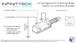
There are some scenarios where you need +12 volts when you foot is not on the brake pedal and ground when you step on the pedal. This picture will show you how to wire the switch.
You are going to wire the MASTERCELL input and its ground the same way that you did for the other example. Then connect one of the NC terminals on the switch to the ignition output on your POWERCELL. Connect the second NC terminal on the switch to your brake signal connection. Lastly, connect a 10K resistor (just like in the previous example) between the brake signal wire and ground. When you foot is off the pedal, you’ll have 12-volts on the brake signal wire. When you step on the pedal, the contacts in the switch open and disconnect the brake signal wire from ignition power. The 10K resistor pulls the brake signal wire to ground. You can download a PDF copy of this diagram by clicking this link.
Click on this link to contact our technical support team if you have any questions about getting a 12-volt brake pedal signal for your transmission controller, cruise control module or PKE system.


