Brake Switch
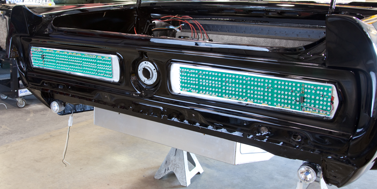
In previous posts, we talked about how to wire the brake lights to the rear POWERCELL in our customer’s 1967 Mustang. We’re going to talk about wiring the brake switch in this post. This is a very easy MASTERCELL switch input to wire. There are lots of different brake pedal switches out there. Here are a few examples from the Summit Racing website.
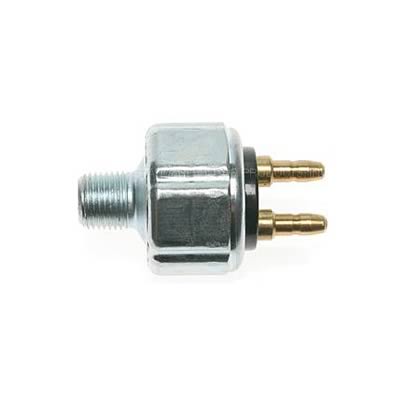
Hydraulic pressure brake switch
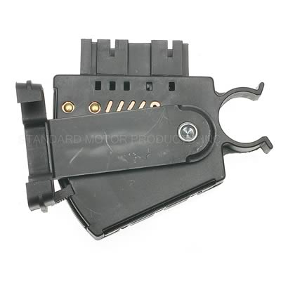
MOPAR-style brake switch
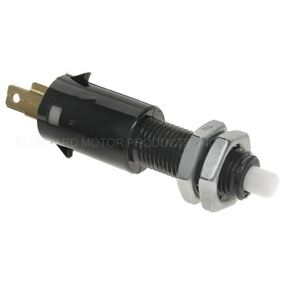
Automotive brake pedal switch
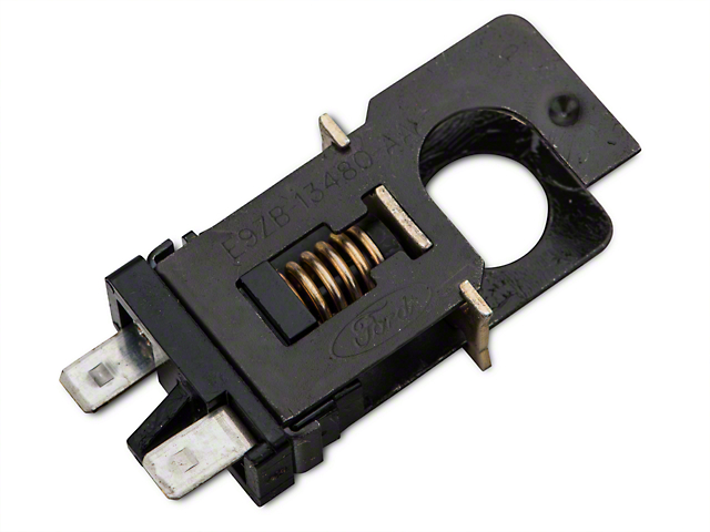
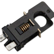
Picture of a lost-travel brake switch. Commonly found in Ford Mustangs.
This last brake switch is what our customer is using in the 1967 Mustang. All of these switches have 2 terminals on them. One will connect to the MASTERCELL input wire. The other will connect to ground. When the pedal is pressed, there is continuity between the MASTERCELL input wire and ground. Refer back to this illustration again.
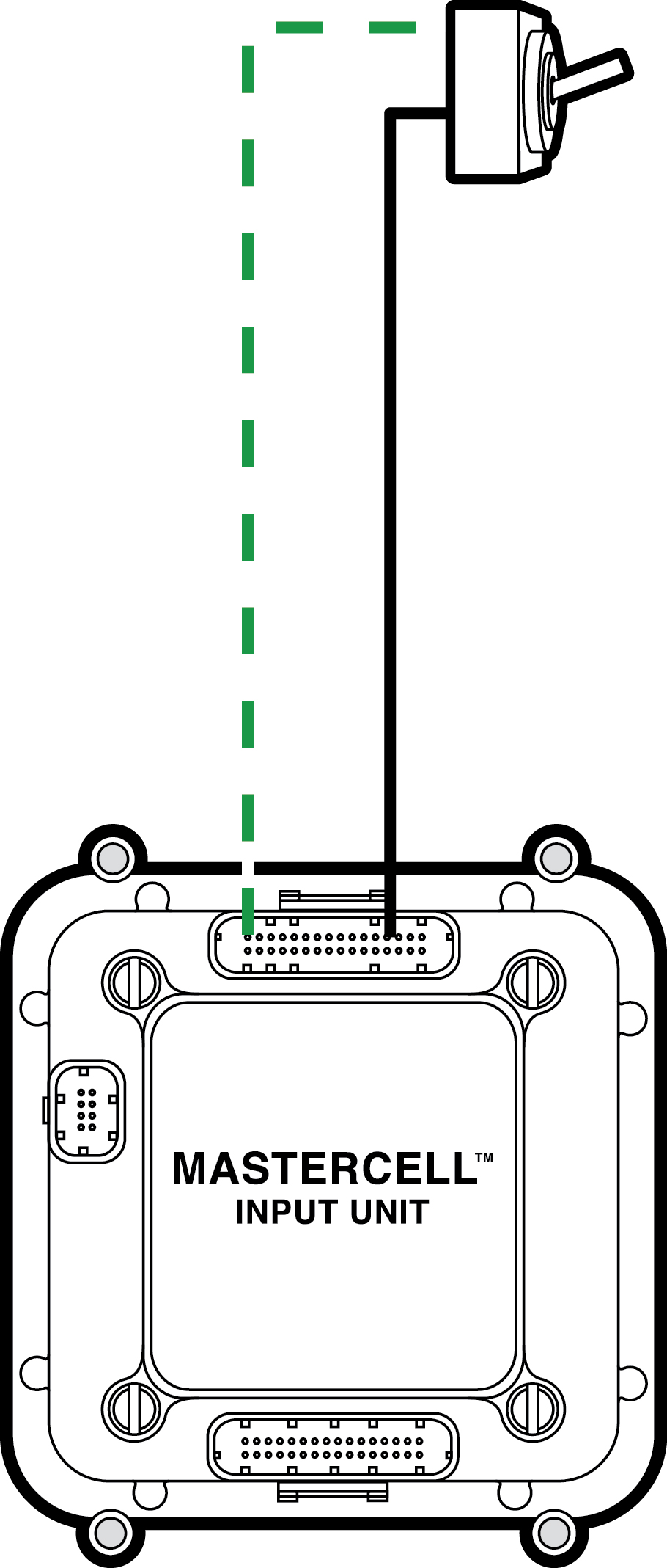
Simple diagram showing how to wire a switch to the Infinitybox MASTERCELL
The brake pedal switch simply connects between the MASTERCELL input and ground.
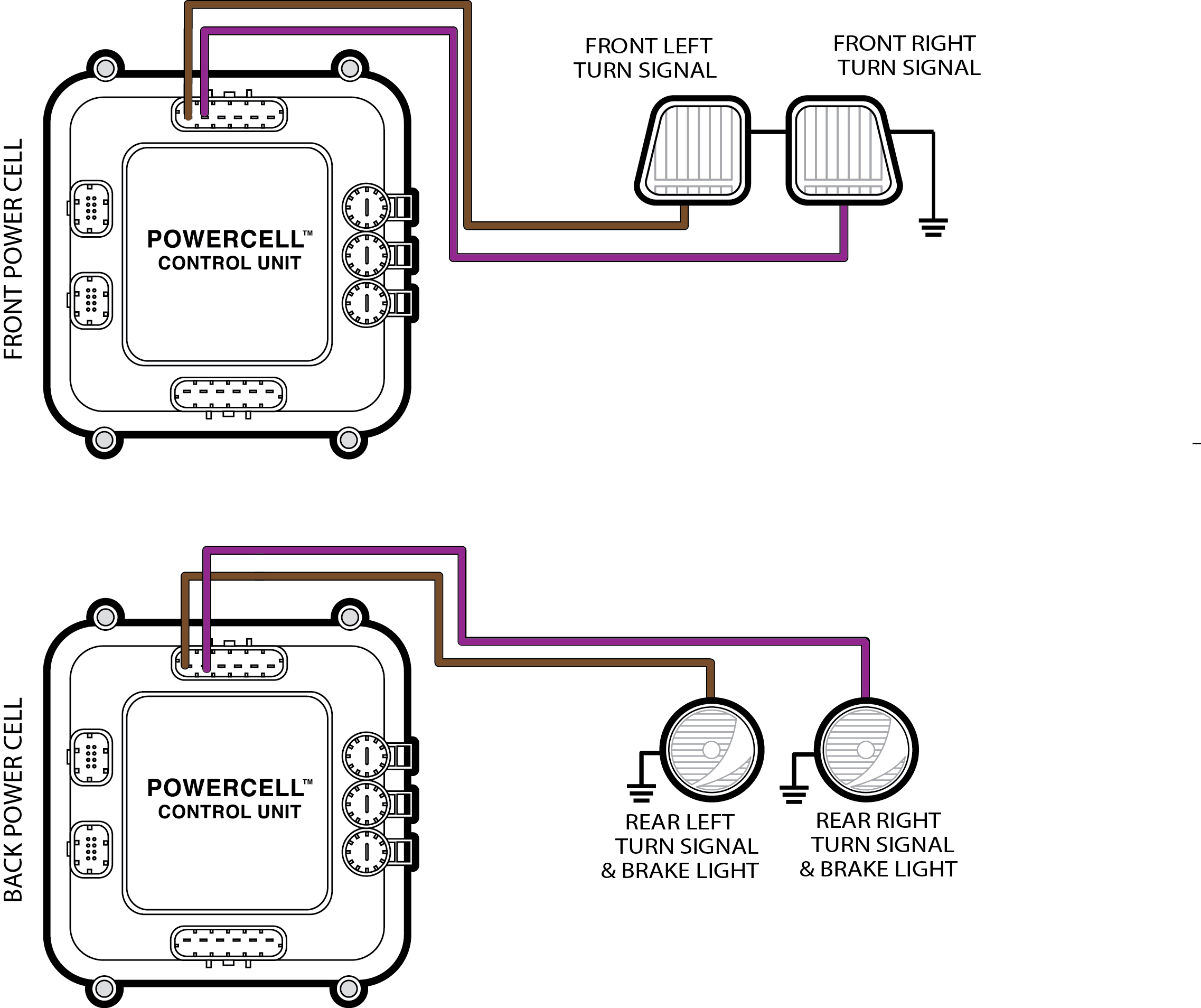
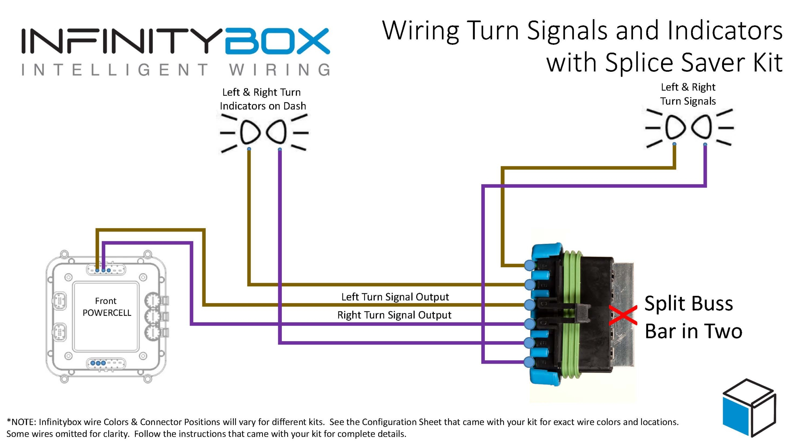
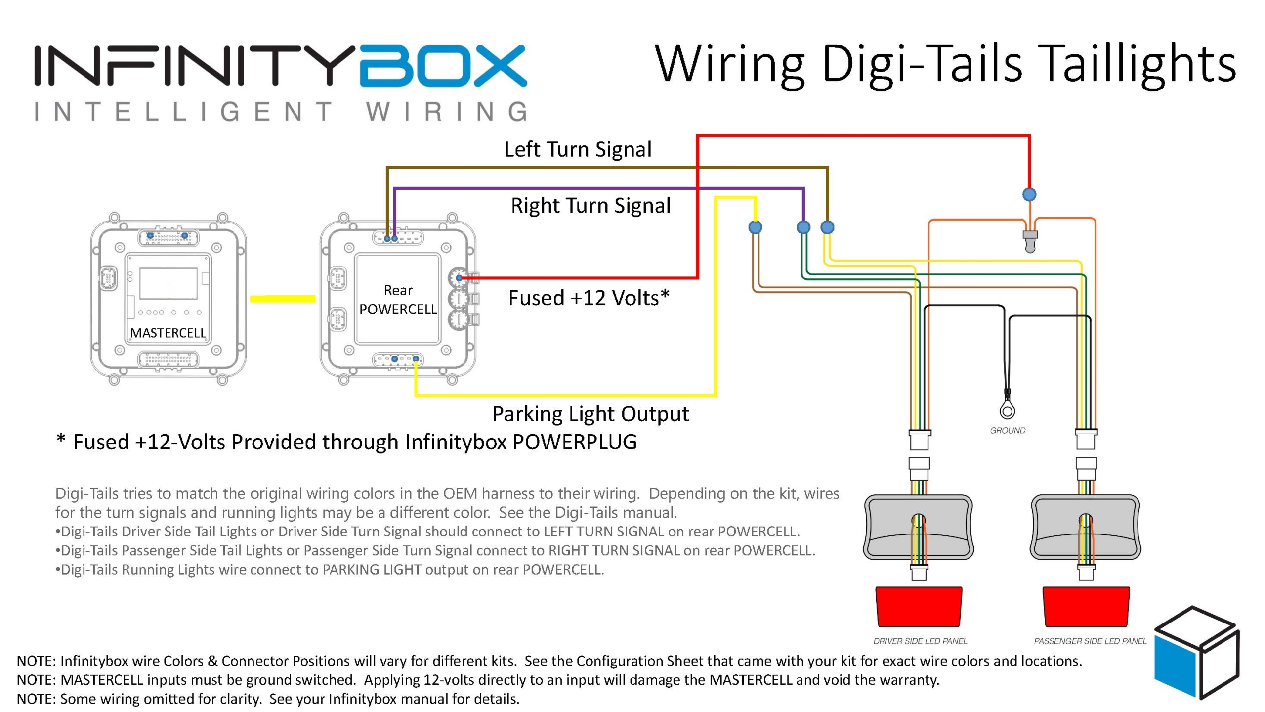
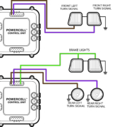
Start by checking the configuration sheet that came with your kit. This link will take you to an earlier post in this series about the importance of your configuration sheet. This car is wired with separate brake light and turn signal outputs on the rear POWERCELL so we’re going to use the MASTERCELL input for Brake Lights with Multi-Filament Bulbs. This post will get you more information on the different turn-signal and brake light options.
We checked our configuration sheet. The MASTERCELL input for the brake switch for the configuration that we want is the Yellow-Green wire. This is input 15 on the MASTERCELL A connector. Remember that the MASTERCELL input wire needs to connect to one side of the switch. The other side of the switch needs to connect to ground. In the case of the brake switch, there is no polarity. You can connect the MASTERCELL input to either of the terminals on the switch.
In the case of the Mustang switch, you can purchase the mating connector and harness that plugs onto the back of the switch. This has the two wires that connect to the MASTERCELL input and ground. You can splice or solder these wires in any way as described in previous posts in this series.
For the ground connection, you have two options. You can make the ground connection directly to the chassis at the brake pedal. Make sure that this connection is made on the body, not on the brake pedal mechanism. You will not get good continuity to ground through the pedal linkage. Put a ring terminal on the ground wire to connect to the chassis. Make sure that you have a metal-to-metal connection for this ground. The junction should be free of dirt, grease, oil, rust, paint, powder coating or any other contaminant.
You also have the option to use any of the black wires in the MASTERCELL harness as your ground connection. There are 8 black, ground wires in the MASTERCELL A harness. All 8 of these wires are electrically the same. You can use any of them to be the ground connection for your brake switch.
Here’s how your brake light circuit will work when it is connected. When you step on the brake pedal, the contacts in the brake switch close. This connection takes the MASTERCELL brake input and connects it to ground. The MASTERCELL detects that the input has been grounded and sends a command to the POWERCELL in the rear of the car. The POWERCELL receives this signal and turns on the output for the brake lights. When you take your foot off of the brake pedal, the contacts in the brake switch open. This disconnects the MASTERCELL input from ground. The MASTERCELL sees this input turn off and sends a command to the rear POWERCELL. The rear POWERCELL gets this command and turns off the brake lights. It seems complicated, but it isn’t. All of this is automatically managed from within the Infinitybox system.
If you have questions about connecting your brake switch, you can click on this link to contact a member of our team. Keep watching our blog for more updates on wiring switches in our customer’s 1967 Mustang.
 Copyright Infinitybox, LLC 2021. All Rights Reserved.
 Copyright Infinitybox, LLC 2021. All Rights Reserved.