Our Infinitybox system offers you the broadest level of electrical control for your hot-rod, street rod, resto mod, kit car, component car and Pro-Touring build. No other wiring harness can do what the Infinitybox system can do. One of our most popular accessories is inVIRONMENT.
Our inVIRONMENT module is a revolutionary connection between your Infinitybox system and a Gen IV climate control system from Vintage Air. Using our inTOUCH NET and inVIRONMENT, you can completely control your heating and air conditioning from a smart phone or tablet in your car. You can control the blower fan speed, the temperature and the blend from a simple and intuitive touch screen interface. You can learn more about the inVIRONMENT module by clicking this link.
This video will show you the features of the inVIRONMENT module.
https://www.infinitybox.com/wp-content/uploads/2021/02/Infinitybox-Video-inVIRONMENT.png7201280adminhttps://www.infinitybox.com/wp-content/uploads/2021/02/infinitybox-logo-https-1-1.pngadmin2020-01-22 21:00:162021-02-25 21:07:46inVIRONMENT Video
Here’s a quick follow up blog post to the one that we just did on trinary switches for air-condition systems. A lot of guys want to know how they wire power to their Gen-IV heating & air-conditioning system from Vintage Air. This post is going to his the basics about Vintage Air wiring with our Infinitybox system.
There are two power connections that you need to make for the GEN-IV. The first is a connection directly to the battery for constant +12-volts. This is the large-gauge red wire in their harness. It has a circuit breaker in-line to protect the wire from overloads. Per their instructions, they recommend that this red power feed gets connected directly to the battery to minimize any voltage drop.
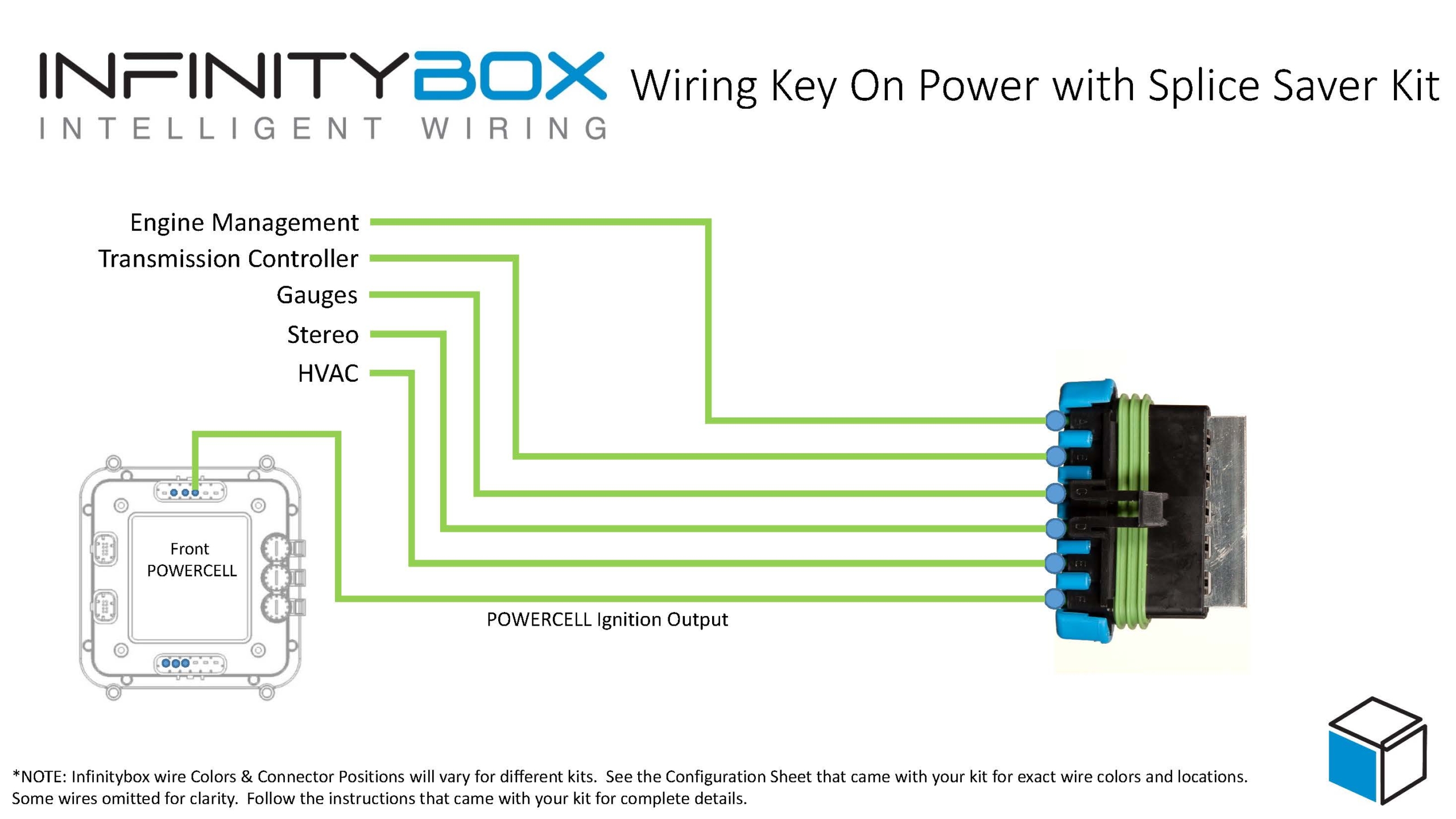
The second connection is for the ignition power for the system. On most of their systems, this is a violet wire in their harness. This ignition feed wire gets connected to the ignition output on your POWERCELL. When the ignition is on, this wire has to have battery voltage on it to turn on the Vintage Air GEN-IV. The majority of the current required to operate the GEN-IV is coming from the direct connection to the battery. This ignition trigger wire requires very little current and can be spliced into the ignition output on the POWERCELL directly. You do not need to add a relay for this.
You can splice this violet wire directly into the POWERCELL output wire. You can also create a terminal block for your switched ignition feeds. The best option it to use our Splice Saver Kit to create a secure and sealed ignition bus.
Wiring ignition key-on power with the Infinitybox Splice Saver Kit
Lastly, you need to make sure that you have the grounds properly connected for the Vintage Air harness. In their wiring diagrams, these are the white wires.
These instructions are applicable for any version of the Infinitybox system, whether or not you’re using inTOUCH NET or inVIRONMENT.
https://www.infinitybox.com/wp-content/uploads/2021/02/GEN-IV.jpg7701600adminhttps://www.infinitybox.com/wp-content/uploads/2021/02/infinitybox-logo-https-1-1.pngadmin2017-04-17 11:52:382021-02-24 11:55:40Vintage Air Wiring
Okay guys, we get asked this question a lot. How do you wire a trinary switch on a Vintage Air Gen-IV with the Infinitybox system? It is a good question. We’re packing a lot into this blog post so hang on. This post is only going to cover wiring the cooling fan part of the trinary switch. The rest of the wiring is going to follow the directions given to you with the Vintage Air Kit. That being said, you must carefully read and understand all of the installation instructions that came with your heating & air-conditioning kit.
Before we get too far, it is important to understand what a trinary switch does. It is a safety switch for air-conditioning systems. It is a three-function switch (tri-nary). It automatically shuts off the power to the air-conditioning clutch if the refrigerant pressure gets too high or too low. It will also automatically turn on the engine cooling fan when the compressor is running. The Vintage Air guys have a great video featuring Rick Love talking specifics about Trinary Switches. You can see that here.
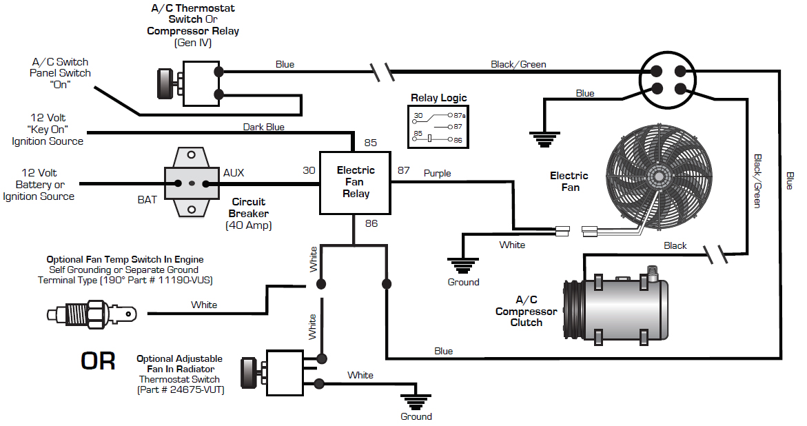
You can see a more detailed picture of the Vintage Air wiring diagram in the picture below.
Your Infinitybox system is going to control your cooling fan. There is a MASTERCELL input that connects to a thermostatic switch on your engine. When the coolant temperature exceeds a set point (usually around 180 F), this temperature switch closes and grounds the MASTERCELL input for the cooling fan. When this happens, the MASTERCELL sends a command to the front POWERCELL to turn on the cooling fan. We’ve blogged about controlling fans before. This link will take you to this blog post.
When you’re installing air-conditioning in a car, you want the cooling fan to turn on under two conditions. First, when the coolant temperature exceeds the set point of the thermostatic switch. Second, you want the cooling fan to turn on when the A/C clutch is running. Running the air-conditioning compressor increases the load on the engine. Also, you have to make sure that you have good air flow through the condenser to make sure that the refrigerant system is working efficiently and safely.
Take a close look at the wiring diagram from Vintage Air. The part of the diagram that we’re going to focus on only relates to the cooling fan wiring. You are going to wire the A/C thermostat through one set of contacts on the trinary switch to the A/C clutch. The Infinitybox system won’t get in the middle of this part of the circuit. If the refrigerant pressure gets too high or too low, it will disconnect power to the A/C clutch for safety.
The fan part of the circuit is what we are discussing. There are a pair of blue wires on the trinary switch. These are the contacts for the cooling fan. One of the blue wires connects to ground. Either of the blue wires will work for this ground connection. In the Vintage Air diagram, you will see that the blue wire on the trinary switch is used to ground switch the coil of the cooling fan relay. When the pressure of the refrigerant in the system exceeds the set point of the trinary switch it will close its contacts and connect the fan trigger to ground.
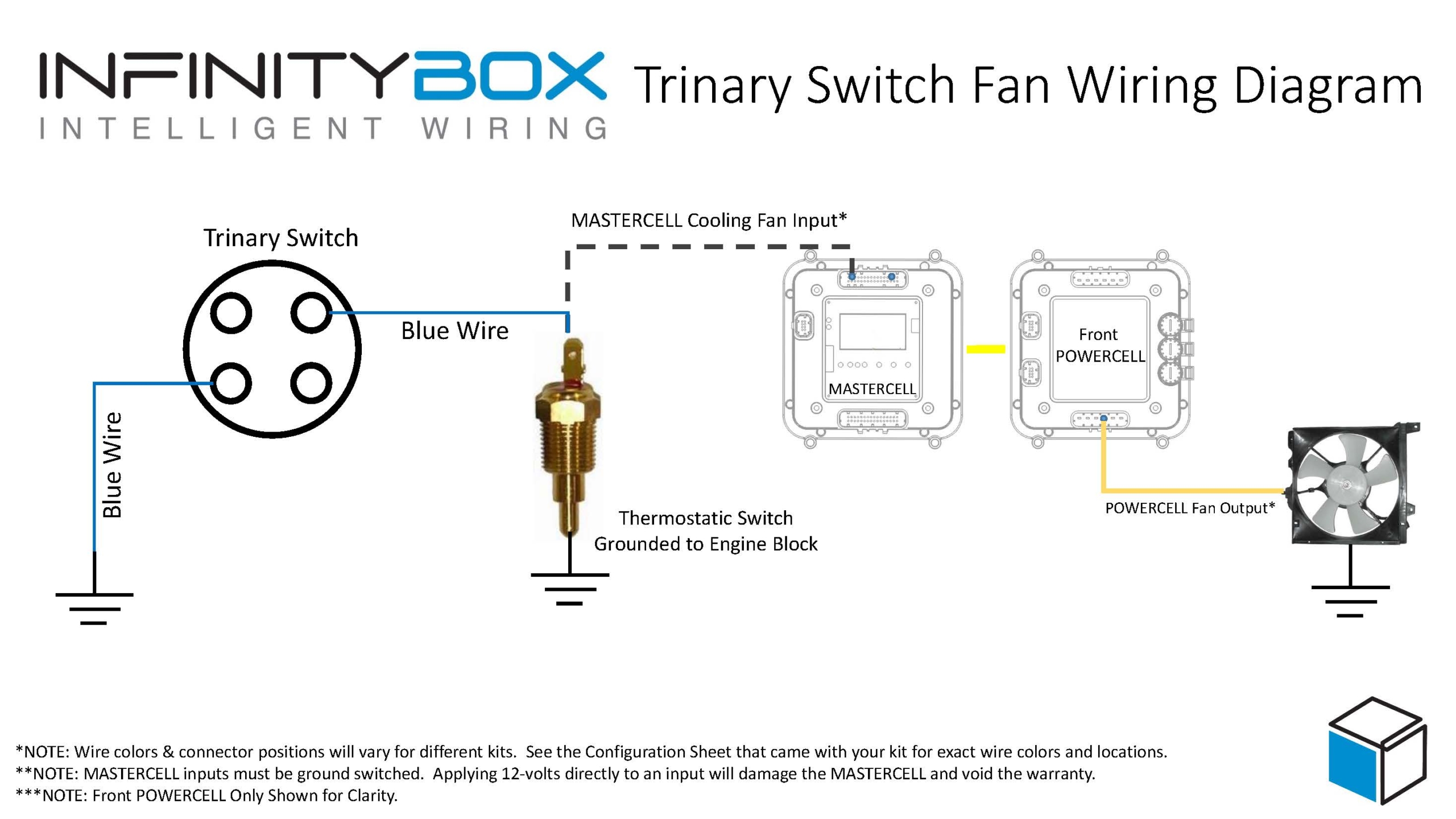
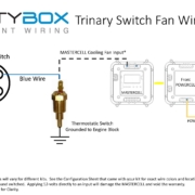
With your Infinitybox system, there are no relays. The MASTERCELL is your trigger and the POWERCELL turns on the power to the fan. The following diagram will show you how to wire the fan contacts of the trinary switch to the MASTERCELL input for the cooling fan.
Picture of wiring diagram showing how to wire a trinary switch into the cooling fan circuit with the Infinitybox system
You will note that the trinary switch is wired in parallel with the thermostatic switch installed on the engine. That way the cooling fan will turn on if either the coolant temperature is high or if the A/C compressor is running. You can splice the trinary wire anywhere into the MASTERCELL cooling fan input wire. You can splice these wires together at the MASTERCELL connector. You can splice the two wires together in the connector going onto the thermostatic switch. Electrically, they just need to be wired in parallel.
 Copyright Infinitybox, LLC 2021. All Rights Reserved.
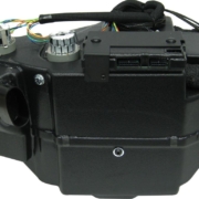
 Copyright Infinitybox, LLC 2021. All Rights Reserved.