Wiring Switches
It is time to get into the next phase of wiring this 1967 Mustang with our Infinitybox 20-Circuit Kit. We got the cells mounted, mounted the Mega fuses, wired primary power from the battery, ran the CAN cable and wired the outputs to the POWERCELLs. It’s time to start wiring switches to the MASTERCELL inputs.
Here’s a quick refresher. Our Infinitybox system is different than any other wiring harness on the market. Instead of having one central box full of fuses and relays with wire running everywhere in the car, our system is broken into smaller modules. Our POWERCELLs are mounted in the front and rear of the car. They contain the fuses and relays to turn your accessories on and off. The MASTERCELL connects to the switches. You mount the MASTERCELL under the dash and wire your switches to it. The MASTERCELL sends commands to the remote POWERCELLs through our CAN cable to control your lights, fans, fuel pump, horns, ignition, starter solenoids and other switched functions. This is going to be the first in a series of posts talking about wiring switches.
Remember that all of your switches will connect to your MASTERCELL. This includes switches for your ignition, starter, turn signals, brake lights, headlights, parking lights, high-beams, cooling fans, fuel pump, horn and anything else that you need to turn on and off in the car. There is no direct connection between your switch and the output. The MASTERCELL watches all of the switches. When it sees a switch turn on or off, it sends a packet of data through the CAN cable to the remote cells in the car. These cells could be POWERCELLs or inMOTION cells. The remote output cells are what control the current flowing to your switched loads.
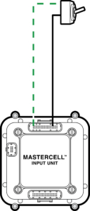
The MASTERCELL needs a simple trigger signal from each switch. These triggers are a connection to ground. Each trigger takes a very small amount of current to send the signal to the MASTERCELL, less than 0.001-Amp. This picture shows a very simple switch wired to a MASTERCELL input.
In this diagram, the MASTERCELL input wire connects to one terminal of the switch. The other side of the terminal needs to connect to ground. When the switch is on (closed) there is a path through the switch to ground. This is what triggers the input on the MASTERCELL. This picture shows using one of the ground wires that is included in the MASTERCELL input harness.
There are lots of advantages to using this kind of input when you are wiring a car. Ground switching the inputs means that you do not need to run a positive wire to each switch. The MASTERCELL input harnesses have ground wires that you can use for your switches. You can also use the chassis in the car as the ground reference for your switches. You just need a good metal-to-metal connection to ground.
Another advantage is that it takes a very small amount of current to turn on an input. This means that we can use a much smaller gauge of wire in the input harness. We use 22-AWG TXL wire on the inputs. This will reduce the bulk of harness behind your dash. It also means that there is no high-current behind your dash. All of the high-current control is at the POWERCELL. It is always the small signal current through the MASTERCELL input wire regardless of what is being switched at the POWERCELL. This means that you can use practically any switch to turn things on and off in your car. You can use the original switches that came with the car. You can use any aftermarket switch. There is very little current flowing through the switch.
Just a quick warning: The MASTERCELL inputs are designed to be switched to ground. You must not wire your switches so that battery voltage can be applied to a MASTERCELL input. Doing this may damage the circuitry inside the MASTERCELL and this will void the warranty. Contact us with questions if you are uncertain about how to properly connect something to a MASTERCELL input.
Remember that your configuration sheet is your road map to wiring your car with our Infinitybox system. Your configuration sheet will identify the wires by color for each of the switches in your car. You can click on this post to get a refresher on your configuration sheet.
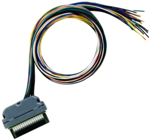
Every kit comes with a MASTERCELL A input harness. This picture shows this harness.
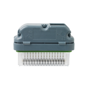
All of your switches will connect to the wires on this harness. The B connector socket at the bottom of the MASTERCELL must have the input dummy plug installed to keep the cell sealed. This picture shows the MASTERCELL input dummy plug.
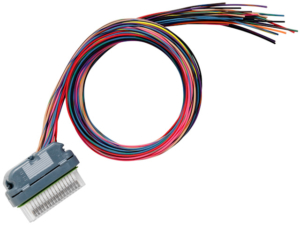
If you have a third POWERCELL as part of your system or if you have added inMOTION to your kit, you will get the MASTERCELL B harness. This picture shows this harness.
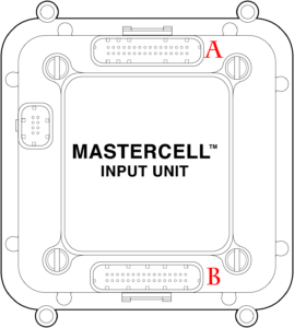
Your configuration sheet will show which harnesses have the inputs for your different switches. This picture shows which is the A & B input connector socket on your MASTERCELL.
In the case of this 1967 Mustang project, the MASTERCELL is mounted under the dash, to the left of the pedals. The input wires will run from the MASTERCELL to all of the switches. This is a great location for this because all of the wire runs will be short.
We will be going through wiring switches in much more detail over upcoming blog posts. Please keep watching our blog for updates. You can click on this link to contact a member of our team with any questions.

 Copyright Infinitybox, LLC 2021. All Rights Reserved.