Our customers are very creative. They are looking for the latest electrical features in their restorations, resto-mods, street-rods, kit cars and Pro-Touring builds. The Infinitybox system is the only electrical system on the market that can get them the flexibility and the power to fulfill their most creative requirements for their cars and trucks. We just got this example from Charlie B. He’s restoring a 1971 Corvette and wanted to integrate a Passive Keyless Entry system into his car. Check out how he did it with our Infinitybox system.
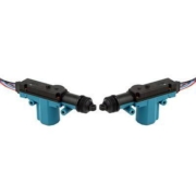
Charlie is wiring his Corvette with our 20-Circuit Kit. He wants to integrate as many of the C6 Corvette features as he can into his car. This includes the Passive Keyless Entry feature and the power door latches found in newer cars. He purchased a set of the C6 door latches and fabricated them into the B-pillars of the car. These latches take a 12-volt signal to let you open the door. He also purchased the C6 door handles that have switches built into them. When you pull on the handle, it closes a switch that is designed to send a signal to the C6 body computer to trigger the latches. In this case, our Infinitybox system replaces the body computer from General Motors.
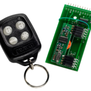
Charlie also purchased the Directed 2102T Passive Keyless Entry System. He wants to replicate the features of the modern Corvettes in his resto-mod. When he is away from the car, he wants it to be secured. The doors can’t open and the car cannot start. When he approaches the car, he wants to be able to pull on the handles to open the doors and press a button to start the engine. Our Infinitybox system lets him do all of this.
Even before you get into the Passive Keyless Entry integration, our Infinitybox system has a built-in one-button start feature. From a single button you can manage your ignition and starter. You can click on this link to learn more about our One-Button Start. This makes Charlie’s one-button start requirement easy. It is standard with every Infinitybox kit.
The 2102T has an output that is called the Starter Kill Output. It is on the 10-position black connector on the 2102T harness. The Starter Kill output does exactly what it sounds like. It is a ground switched output, designed to interrupt the starter relay in the car. It connects to the ground side of the relay coil. When the PKE transmitters are out of range of the car, this circuit opens to disable the ability to crank the starter. When the PKE transmitters are in range of the car, the Starter Kill Output closes and creates a path to ground for the starter relay. This lets you start the car.
In Charlie’s case, he wants to limit the ability to open the doors of the car and start the car using our one-button start. For all of these switches, he used the Starter Kill Output on the 2102T to interrupt the ground path for his one-button start switch and the switches for his doors. The following diagram shows the details.
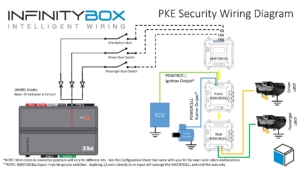
Image of Infinitybox wiring diagram showing how to limit MASTERCELL inputs using the Directed 2102T Passive Keyless Entry System
Our MASTERCELL inputs are triggered by a connection to ground. You connect the input to your switch then ground the other side of your switch. Turning on the switch closes the circuit to ground, which turns on the MASTERCELL input. The MASTERCELL then sends a command to the POWERCELLs in the system to control your outputs. This link will get you more detail on how the MASTERCELL inputs work. If anything interrupts the electrical path from the MASTERCELL input to ground, the MASTERCELL input will not turn on. Charlie’s using the Starter Kill Output on the Passive Keyless System to interrupt the ground path to control when his switches will work.
For his one-button start, he connected the MASTERCELL input to one side of his switch then connected the ground side of this switch through a diode to the Starter Kill Output. He will only get a path to ground for the one-button start switch when his PKE transmitter is in range of the car. When the transmitter is out of range, pushing the one-button start will do nothing.
For his door latches, Charlie picked two open outputs on his rear POWERCELL. He wired these outputs to the door latches in the B-pillars and grounded the latches to the chassis. Then he took the MASTERCELL inputs that corresponded to the POWERCELL outputs and connected them to the switches in the door handles. Instead of grounding the door switches to the chassis, he connected the ground side of the switch to the Engine Kill Output on the 2102T with a diode in series. When he pulls on the door handle, the switch in the handle closes. The MASTERCELL input will get connected to ground when the PKE transmitter is range and the Starter Kill Output is on. This will cause the MASTERCELL to send a command to the POWERCELL to send 12-volts to the door latch to open the door.
The diodes in this circuit are very important. They isolate the three inputs from each other so that they can operate independently. Without these diodes, all three MASTERCELL inputs would turn on if you turned on any one of the switches. The diodes that we recommend are 1N4001 and can be purchased from any on-line electronics seller. The orientation of the diodes are very critical. Diodes are like check valves and they must be oriented in the correct direction. For this circuit, the cathode must be oriented away from the MASTERCELL input. The cathode end is the one with the stripe on it.
This simple wiring set up gives Charlie all he wanted for his car security. If anyone walks up to the car without his PKE transmitters, they can pull on the door handles and nothing will happen. The doors will not open. If they were to get inside the car and press the one-button start, nothing would happen. The car would not start.
If Charlie approaches the car with his PKE transmitters, the 2102T activates and enables the switches for the doors and the one-button start. He can pull on the door handle and the doors will open. He can get in the car and press his one-button start. The engine will start. All of these features are exactly like what you get in a modern Corvette.
You can download a PDF of this wiring diagram for your project by clicking this link.
Please click this link to contact our technical support team if you have any questions about wiring your car or truck with our Infinitybox system.
 Copyright Infinitybox, LLC 2021. All Rights Reserved.
 Copyright Infinitybox, LLC 2021. All Rights Reserved.
 Copyright Infinitybox, LLC 2021. All Rights Reserved.
 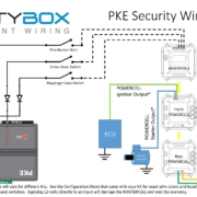 Copyright Infinitybox, LLC 2021. All Rights Reserved.
 Copyright Infinitybox, LLC 2021. All Rights Reserved.