Here’s the first step in our 1967 Mustang wiring project. It is mounting the fuses that protect the power feeds going to the POWERCELLs. In our 10 and 20-Circuit Harness Kits, we give you a block of Littelfuse Mega fuses to protect the 8-AWG cables that power the cells. In our Express Racing Kits and with our inMOTION cells, we give you a JCASE holder instead of the Mega block.
These fuses serve a very important purpose. They protect the 8-AWG cables from short-circuits or low overloads. The fuse in any circuit is supposed to be the weak link, electrically. They are thermally operating devices that are designed to open and clear the circuit if too much current flows. Wires can be fuses too, which is a bad thing. If too much current flows through a wire, it will heat up. As the wire heats up, the insulation can melt causing fire or other damage in the car.
As mentioned above, the fuses ultimately protect against two things. The most common is a short circuit to ground. If the insulation on the wire were to become damaged and the conductor were to touch the chassis, you have a very low resistance path to ground. The insulation can become damaged over time by rubbing against a sharp edge or can be connected to ground quickly in an accident. You can also accidentally drop a tool across an open set of terminals and make a good short to ground. (We’ll admit that we’ve done that before.) The second thing that the fuse protects against is a low-overload. These are usually resistive connections to ground. They are not as common as a short circuit.
Car batteries have a tremendous amount of stored power in them. A low resistance path to ground will allow a lot of current to flow. This current flow causes heating in the wire. As mentioned above, the fuse is designed to open (blow) before the wire gets hot enough to cause damage. The Mega fuses in your kit are sized at 60-Amps. A 60-Amp fuse is the proper rating to protect an 8-AWG cable.
We have many different blog posts about fusing. Here is a good one for your reference.
In the case of this 1967 Mustang, the battery is in the trunk. The customer mounted the Mega fuse block against the trunk wall, towards the driver’s side of the car. Here’s a picture of the fuse block mounted in the trunk.
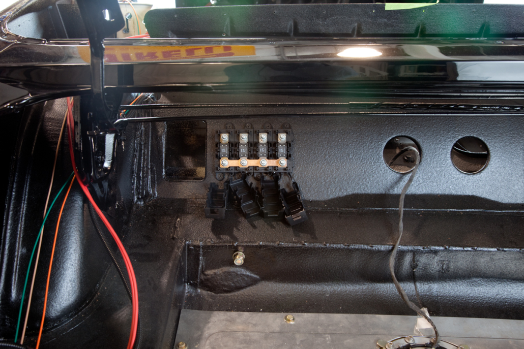
Location of Mega Fuse Block in 1967 Mustang wired with the Infinitybox system.
You want to make sure that the Mega fuse block is securely mounted in the car. There are mounting holes on the top and bottom of the holders. We recommend using nuts and bolts with lock-washers to mount this to a flat surface like the one shown in the picture above. Self-tapping screws will work too but aren’t as reliable as a bolt & nut with a lock-washer.
You want to have reasonable access to the primary fuses in the car. Over its lifetime, you should really never have to change these fuses. If you ever were to blow one, that means that something bad has happened. You have either been in an accident and one of the cables has broken to ground or the insulation on one of the cables was worn over time.
You want to mount the fuses as close to the battery as possible. The purpose of this is to minimize the length of unprotected wire in the circuit. The unprotected wire is the wire between the power source and the first fuse. We give you the Mega fuse block, the ring terminals, the 8-AWG cables and a 4-AWG cable in your kit. You use the 4-AWG cable to connect the battery to the buss bar on the fuse block.
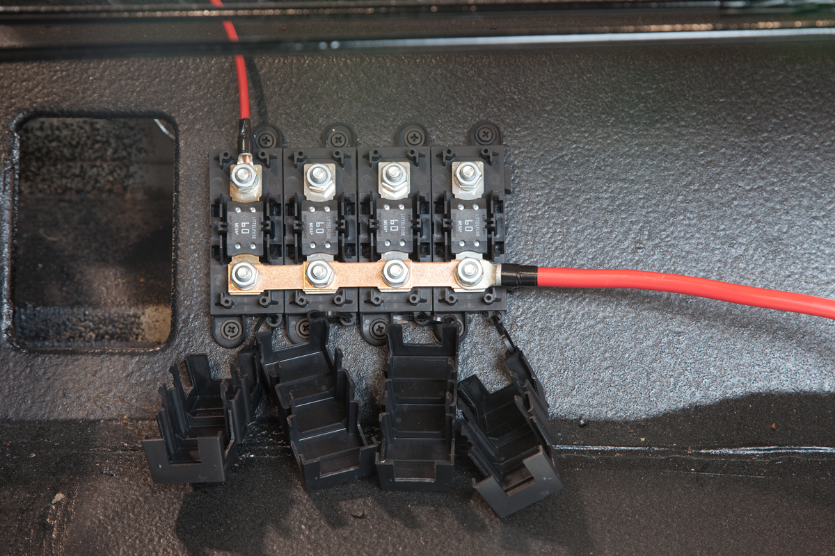
This picture shows the 4-AWG wire connected to the buss bar on the Mega fuse block. The customer crimped the included ring terminal on the end of the 4-AWG wire and connected that to the buss bar. The other side of this 4-AWG cable connects to the positive side of the battery. This connection can be made directly to the battery, to a primary disconnect switch or to our inRESERVE battery management solenoid. Please note that we strongly recommend a battery disconnect, either a manual switch or our inRESERVE kit.
Also, note that they used heat shrink tubing to protect the exposed part of the terminal. This is recommended to reduce the chance of shorting this side of the fuse block to the chassis.
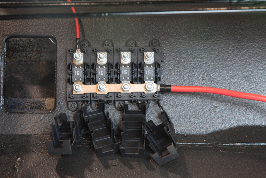
Primary battery cable connected to Mega Fuse block in 1967 Mustang wired with the Infinitybox system.
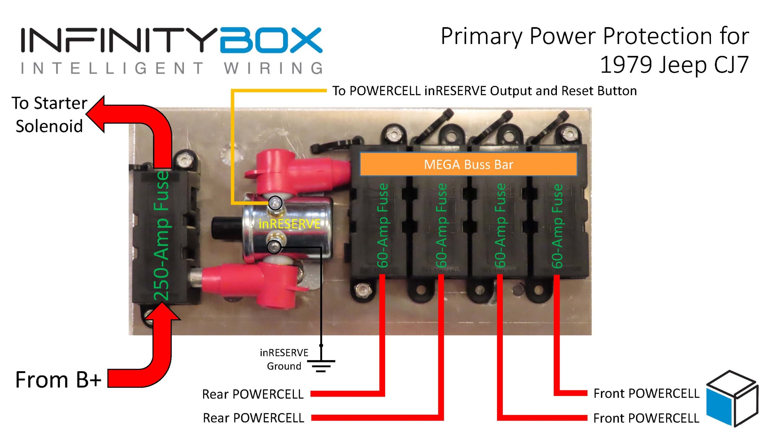
Just a quick warning about connecting the Mega fuse and 8-AWG power feeds. You want to connect all of the POWERCELL feeds back to the same Mega fuse holder. This Mega fuse holder should be connected to the battery either directly or through a disconnect solenoid. You must not connect power to your Infinitybox system to the starter cable at the starter motor. This is our recommendation and that of most other electronics manufacturers. There are surges and transients associated with the starter motor that could interfere with your ability to start the engine if you are powering the system from the starter cable at the starter motor.
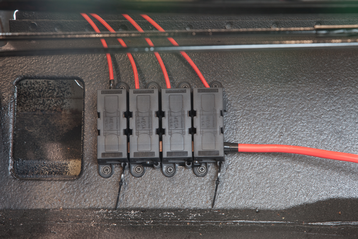
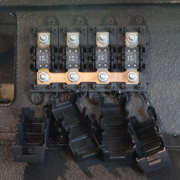
Once the 4-AWG cable is connected, you need to connect the four 8-AWG feeds that go to the POWERCELLs. Each POWERCELL needs two of these feeds. In the case of this Mustang, two of the 8-AWG feeds route to the POWERCELL in the trunk. The other two 8-AWG feeds run to the front of the car to connect to the front POWERCELL. This picture shows the 8-AWG cable connected and the covers snapped in place on the Mega fuse block. You must keep these covers in place to protect the terminals on the fuses from getting accidentally shorted to ground. (Again, we’ve done that before with a wrench.)
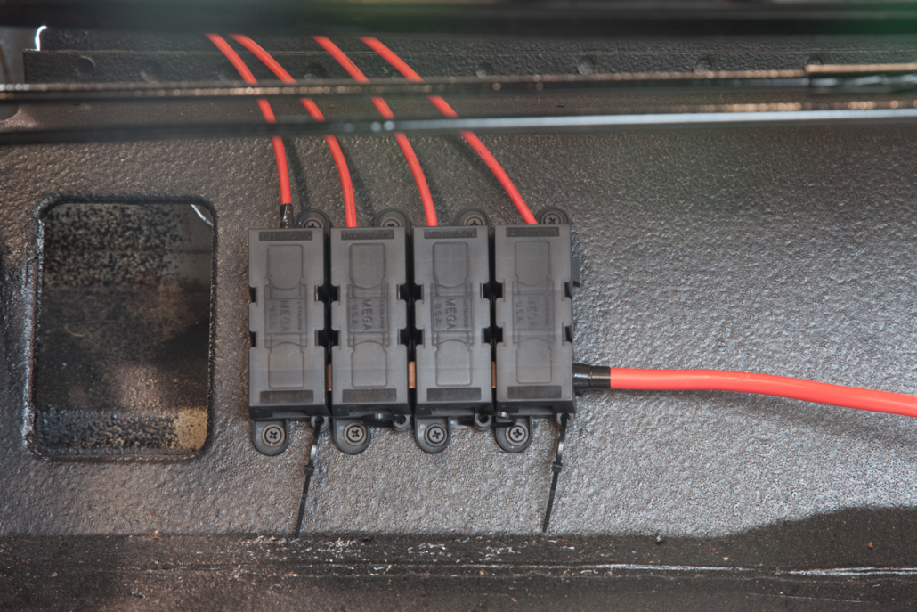
Assembled Mega Fuse block in 1967 Mustang wired with our Infinitybox system
Make sure that all of the bolted connections are tight. Don’t over-tighten these bolts. The recommended bolting torque is 10 foot-pounds. Once that’s done, you’ve finished the job of mounting the fuses. Stay tuned for the next step in the process of wiring a 1967 Mustang with our Infinitybox 20-Circuit Harness Kit. Click on this link to contact us with comments and questions.
 Copyright Infinitybox, LLC 2021. All Rights Reserved.
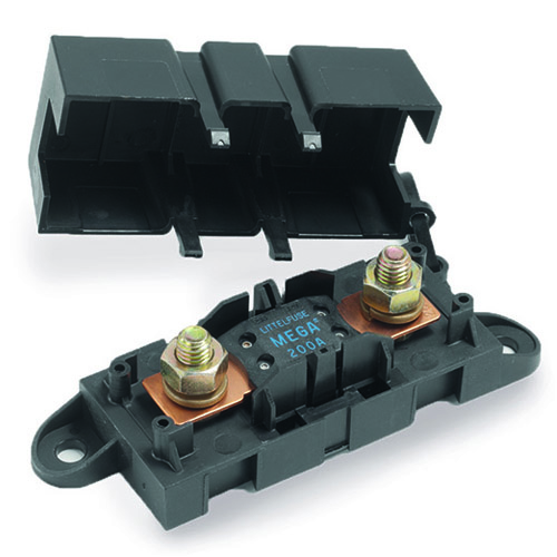

 Copyright Infinitybox, LLC 2021. All Rights Reserved.